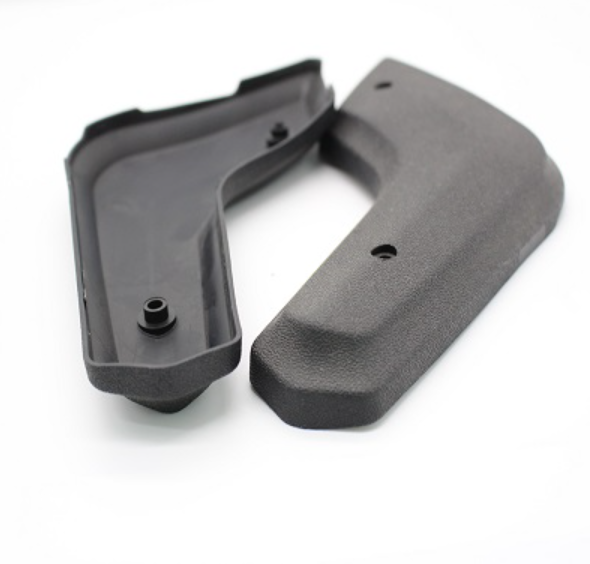
1. The injection mold parts are short of glue and full of mold
Cause analysis: The plastic melt did not completely fill the cavity. The fluidity of plastic materials is not good.
Countermeasures: Improper matching between products and injection molding machine, insufficient plasticizing capacity or injection volume of injection molding machine. The material temperature and mold temperature are too low, the plastic flow is difficult under the current pressure, the injection speed is too slow, and the holding pressure or holding pressure is too low. Insufficient melting and poor fluidity of plastic lead to large injection pressure loss. The number of gates should be increased, the gate position should be arranged reasonably, and the multi cavities should be arranged and filled in an unbalanced way. The nozzle, runner and gate are too small, the process is too long, and the plastic filling resistance is too large. The air can’t be eliminated when the mold exhausts badly.
2. Burr
Cause analysis: The plastic melt flowing into the parting surface or the fitting surface of the insert will occur. The clamping force is enough, but the film like excess compound is produced at the junction of the main runner and the splitter.
Countermeasures: The clamping force is insufficient, and the high-pressure plastic injected into the cavity creates a gap between the parting surface or the mating surface of the insert, and the plastic melt overflows into this gap. The mold does not fully contact the nozzle of the machine, and there is a gap between the male and female molds. The influence of mold temperature on crankshaft-type clamping system. Improve the strength and parallelism of the template. The mold guide column sleeve is worn out/the mold mounting plate is damaged/the tie rod is not strong enough to bend, resulting in the deviation of the parting surface. Foreign matter adheres to the parting surface. The exhaust groove is too deep. The projection surface of the cavity is too large/the temperature of the plastic is too high/the pressure is too high.
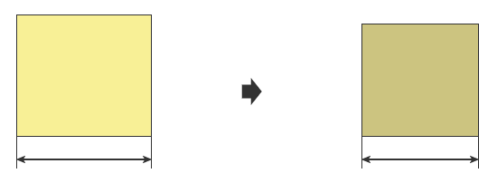
3. Surface shrinkage (vacuum bubble)
Cause analysis: The surface of the product is sunken. It is caused by the shrinkage of plastic volume, and is often found in local fleshy areas, such as stiffeners or the junction area between column and surface. Product local meat thickness in the cooling process, due to volume shrinkage produced by the vacuum bubble, called shrinkage (void). When the plastic melt contains air, water and volatile gas, the air, water and volatile gas enter into the product during the injection molding process, and the residual cavity is called bubble.
Countermeasures: Increase the gate and runner size, so that the pressure can effectively act on the thick part of the molded product. If necessary, the position of the rubber mouth can also be adjusted. Increase the holding pressure and prolong the holding time. Increase the filling speed, the plastic can be fully compressed before cooling and curing. It is too fast for injection to keep pressure. Make the meat thickness change more smooth, and improve the cooling efficiency of this part. The colloidal particles are dried sufficiently in advance to remove moisture. The barrel temperature should not be set too high, which can effectively prevent the generation of plastic decomposition gas. Use small screw or machine to prevent the screw from over shearing. Raise the back pressure so that the gas can be discharged from the barrel. Reduce the filling speed properly, the gas has enough time to discharge.
4. Silver pattern
Cause analysis: Silver white stripes along the plastic flow direction on or near the surface of the product. Silver wire is usually produced by the vaporization of water or volatiles in the plastic or the water adhering to the surface of the mold. The screw of the injection molding machine is involved in the air and sometimes silver bars are produced. There are impurities in the material.
Countermeasures: Insufficient moisture, volatiles and drying of plastics. When the plastic melt overheats or stays in the barrel for a long time, it decomposes and produces a large amount of gas, which is not completely discharged, resulting in silver wire during curing. When the mold temperature is too low, the plastic melt solidifies rapidly, resulting in incomplete exhaust. The surface of the mold is attached with oil or water or release agent, which evaporates into gas and liquefies with the cooling and solidification of the plastic melt. If the screw is involved in the air and the lower part of the hopper is cooled sufficiently, the temperature at the hopper side is low and there is a temperature difference between the screw and the barrel. The rubber particles often scratch the screw and easily bring in the air. Poor exhaust at the beginning of injection. At the beginning of the injection, the plastic melt solidifies rapidly, so the gas is not completely discharged and silver thread occurs. The injection pressure is too high and the injection speed is too fast. When the meat thickness changes dramatically, the compressed plastic melt in the flow rapidly decompresses and expands, and the volatile decomposition gas liquefies after contacting with the mold cavity.
5. Scorch and gas mark
Cause analysis: The so-called burn mark includes the discoloration of the surface of the product due to the degradation of plastic and the blackening of the filling end of the product. Scorch is that the air trapped in the cavity can not be quickly discharged (trapped gas) when the plastic melt is filled, and the material is scorched because it is compressed and heated significantly. Poor exhaust.
Countermeasures: Strengthen the exhaust in the trapped area, so that the air can be discharged in time. The injection pressure should be reduced, but it should be noted that the injection speed will slow down after the pressure drops, which will easily lead to the deterioration of flow mark, weld mark and weld mark.
① Multi stage control filling is adopted, and multi-stage deceleration mode is adopted at the end of forming process to facilitate gas discharge.
② A vacuum pump is used to extract air from the cavity to fill the cavity in vacuum. Clean the exhaust groove to prevent blockage.
③ The gate is too thin or too long, resulting in plastic degradation. P exhaust grooves, exhaust inserts, etc.
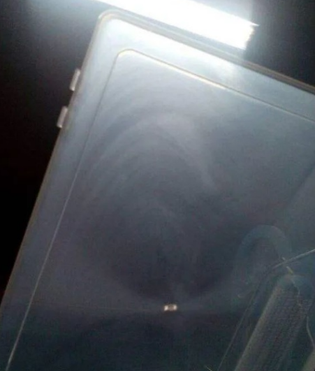
6. Surface flow pattern and water ripple
Cause analysis: The traces of the plastic melt flow are striped waves with the gate as the center. Numerous fine lines in the vertical flow direction occur on the surface, resulting in fingerprint-like ripples on the product surface.
Countermeasures: The flow mark is caused by the fast cooling of the plastic melt flowing into the cavity at the beginning and the boundary between the plastic melt flowing into the cavity and the plastic melt flowing into the cavity later. If the cold material left in the front end of the nozzle of the injection molding machine directly enters the cavity, it will cause flow marks. When the melt temperature is low, the viscosity increases and flow marks occur. Low mold temperature takes away a lot of heat from the plastic melt, resulting in the decrease of the temperature of the plastic melt and the increase of the viscosity. If the injection speed is too slow, the temperature of the plastic melt decreases and the viscosity increases during the filling process, resulting in flow marks. During the filling process of the mold, the temperature of the plastic melt in the mold cavity drops and it is filled with high viscosity. The plastic melt in contact with the mold surface is pressed into the mold in a semi-solid state, resulting in numerous fine lines in the vertical flow direction on the surface, resulting in ripples similar to fingerprints on the surface of the product. When the temperature of the plastic melt drops again, it will solidify if the filling is not complete, resulting in insufficient filling. Waviness often occurs near the edge of the product and at the end of the filling.
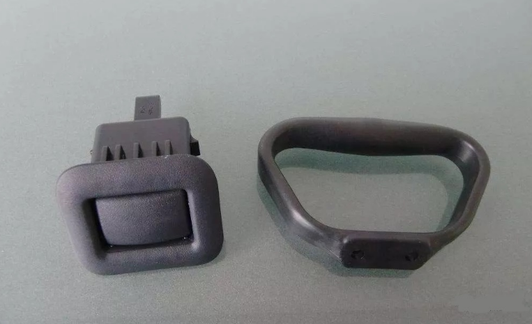
7. Clip water pattern (welding mark), jet pattern (snake pattern)
Cause analysis: When the mold adopts the multi-gate pouring scheme, the rubber flow fronts merge with each other; the hole position and the obstacle area, the rubber flow front will also be divided into two; uneven wall thickness will also cause weld marks . The plastic melt that passes through the gate at high speed directly enters the cavity, then contacts the surface of the cavity to solidify, and then is pushed by the subsequent plastic melt, leaving traces of snakes. Side gate, when there is no stagnant area or insufficient stagnant area after the plastic passes through the gate, it is easy to produce spray marks.
Countermeasures: reduce the number of gates. Add a material overflow well near the fusion part, move the fusion line to the overflow well, and then cut it off. Adjust the gate position. Change the position and number of gates to move the position of fusion line to other places. Strengthen the exhaust in the fusion line area, quickly evacuate the air and volatiles in this part, increase the material temperature and mold temperature, enhance the fluidity of plastic, and improve the material temperature during fusion. Increase the injection pressure and increase the size of gating system. Increase the injection speed. Shorten the distance between gate and welding area. Shorten the distance between gate and welding area. Reduce the use of mold release agent. Adjust the gate position so that the plastic melt will collide with the pin or wall after passing through the gate. Change the gate form, adopt overlapping gate or lug gate, and set enough stagnant area in the gate area. It can slow down the initial injection speed of plastic melt. Increase the gate thickness/cross-sectional area to make the flow front form immediately. Increase the mold temperature to prevent rapid solidification of materials.
 Mold Shrinkage Chart, Formula, Calculation, Plastic Shrinkage Rate | Injection Molding Shrinkage
 Flow Lines In Injection Molding: How To Solve & Prevent | CNCLATHING
 What Causes Dimensional Variations Of Injection Molding And How To Fix
 Classification of 8 Common Plastic Molds in CNC Machining
 Causes & Solutions To Overflow Of Injection Molding Machine Head | CNCLATHING
 Optimization Of Injection Molding Process – Methods To Improve Performance Of Plating On ABS & PC
