China Leading Gear Manufacturing Company – Custom Precision Gears Machining & Fabrication
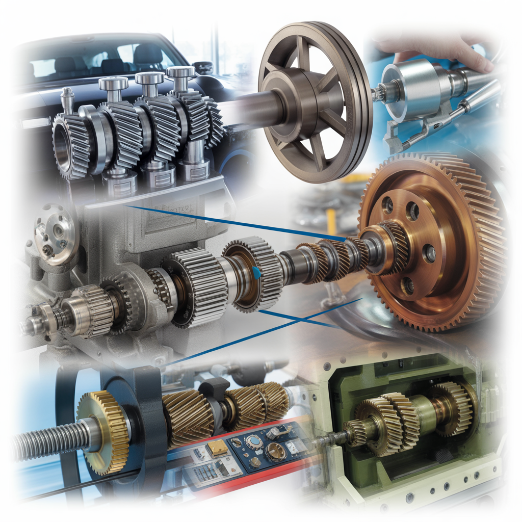
With years of experience in CNC manufacturing and metal machining, Junying has the expertise to produce custom gears with various gear manufacturing processes and techniques. From gear designs to production to shipping, we can meet your requirements at each stage. Our capabilities including gear machining (gear cutting, gear hobbing, gear milling, gear grinding) and gear forming (gear forging, gear extrusion, gear casting, gear injection molding), the cutting edge technologies and advanced gear manufacturing equipment at our factory enable our gear products to achieve the industry-leading standards or exceed the customers’ expectations. Whether you want to find the manufacturers of spur gears, helical gears, spiral bevels, or other types of CNC gears, we’ll deliver top-quality products with a fast turnaround. From hard metals to plastics, a wide selection of materials with excellent properties are provided. We can also help you in the design and review of almost all types of gears to enhance their functionality and manufacturability.
Why Choose Junying for Gear Manufacturing?
- Custom solutions for complex gear manufacturing tasks and technical support
- Well-equipped facilities, seasoned workforce and heavy investment in gear development
- Right expertise and multiple techniques for the production of different types of gears
- Prototypes can be developed and evaluated to improve manufacturing and performance
- Quality inspection services to ensure right dimensions and minimal quality issues
- Work closely with customers to get the most customer satisfied results
What is Gear Manufacturing
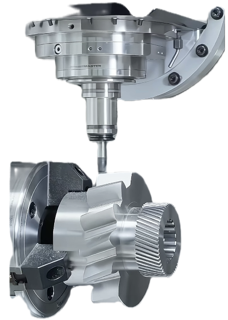
Gear is an important part of mechanical transmission devices. It mainly transmits torque, bears bending, and impacts loads. Its quality will have a direct impact on the vibration, noise and reliability of automobile assembly and even the whole vehicle, and sometimes become the key factor restricting the improvement of product level. Gear manufacturing refers to the process of making gears with a specific structure and accuracy using a mechanical method.
Types of Gear Manufacturing Process
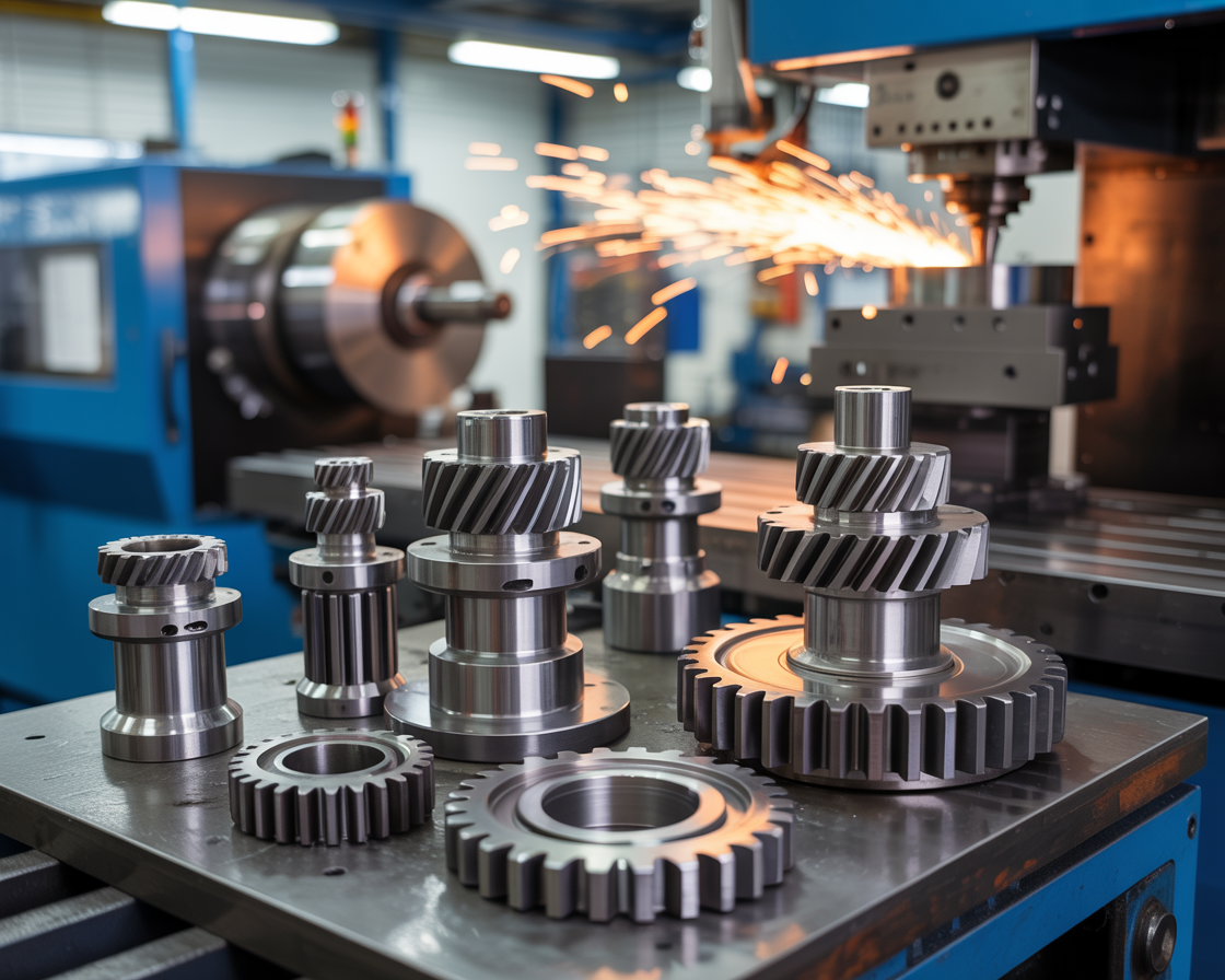
The selection of gear manufacturing process is depending on the application, accuracy requirements, and other actual situations. The gear fabrication processes are mainly divided into two categories: gear machining and gear forming.
1. Gear Forming
Gear forming is the method to produce the teeth on the gear using a mold or die into which the tooth shapes have been machined. The majority of gear forming processes have high tooling costs and are ideal for high volume production. More gear forming processes include sintering, cold drawing, preforming, blanking, etc.
- Gear casting: including die casting, sanding casting and more, most of them are used to produce gear blanks or cast tooth gears, the tooth shape is built into the mold, suitable for a wide range of materials and needs little finishing operations.
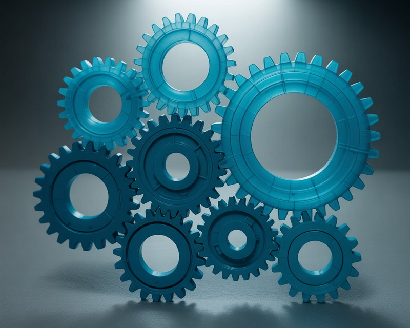
- Gear injection molding: used for the production of plastic gears or nonmetallic gears in washing machines, cameras, projectors, and other applications, common materials are nylon, polyimide, and cellulose acetate. Injection-molded plastic gears generally have low precision, small sizes, and low cost.
- Gear extrusion: often used to produce helical gears, this method forms teeth on long rods which are cut into specific lengths and machined, the advantage of gear extruding is a good surface finish, dense structure and high strength. The main materials for extrusion are aluminum, brass, and copper.
- Gear forging: forging has been used in the manufacture of gears for a long time, mainly for the production of gear blanks, which would subsequently be machined into the desired configuration. Gear forging includes open-die forging, closed-die forging, and hot upset forging.
- Gear stamping: the sheet metal can be stamped with tooth shapes to form gears with low precision.
2. Gear Machining
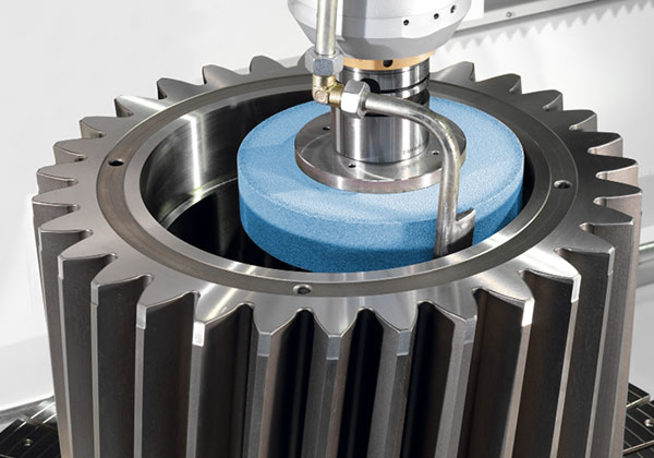
Gear machining is the process of using cutting tools to machine gears from casting, forging, rolling or other forming methods. More gear machining techniques such as gear shaping, shaving, lapping, honing, etc.
- Gear milling: a material removal process that uses a milling cutter to cut the gear blank for creating the tooth gap, the mill cutter shape conforms to tooth spacing, this method can produce almost all types of gears.
- Gear hobbing: the most widely used gear cutting process, a continuous generation process in which the hob teeth rotate about an axis normal to that of the gear blank, cutting into the rotating blank to generate the teeth. The continuous transmission of the hob is like an infinite rack moving continuously. Gear hobbing can be applied for making helical gears, spur gears, and other small gears.
- Gear grinding: a contoured grinding wheel is used to remove a small amount of materials to get a high surface finish.
- Other Gear Machining Techniques: Shaping, broaching, shaving, lapping, honing, etc.
Types of Gears Manufactured
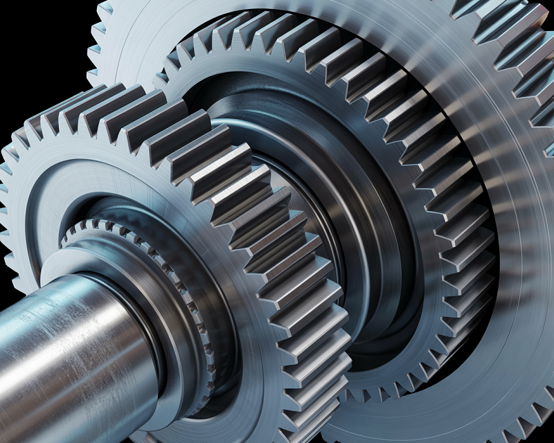
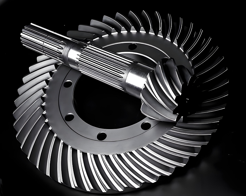
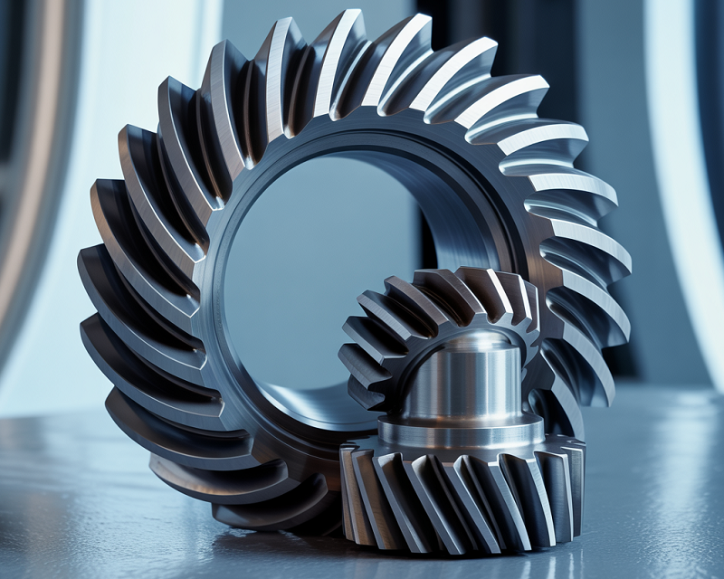
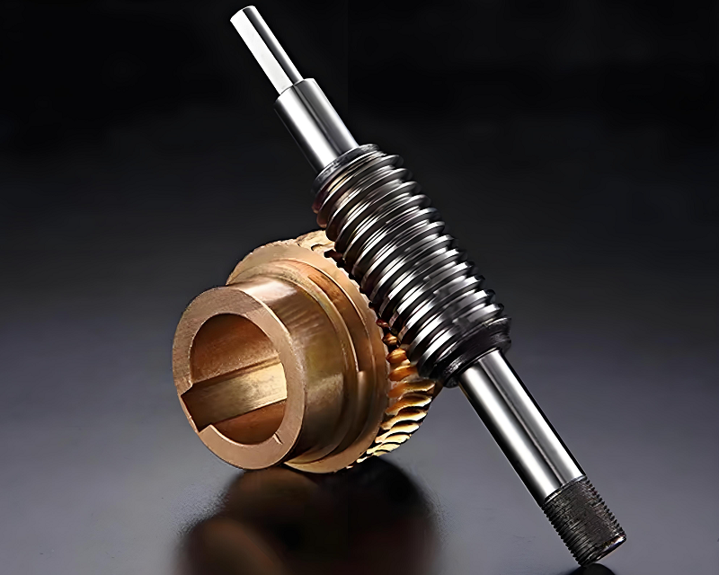
At Junying, our team produces a wide range of gears to fit different engineering requirements and industries. Over the years, we have supplied spur gears for automotive transmissions, helical gears for industrial conveyor systems, and bevel gears for marine propulsion units. Our factory also manufactures worm gears for packaging machinery and planetary gear sets used in robotics and automation. Each gear is machined with care to meet your specifications, whether you need prototypes for testing or a production run for end-use products. Many clients come to us with challenging projects, from compact gears for medical devices to robust drive gears for heavy equipment, and we take pride in delivering reliable solutions every time. Take a look at the gear types we manufacture, and see how we can support your next project.
Spur Gears
Bevel Gears
Helical Gears
Worm Gears
Plastic Gears
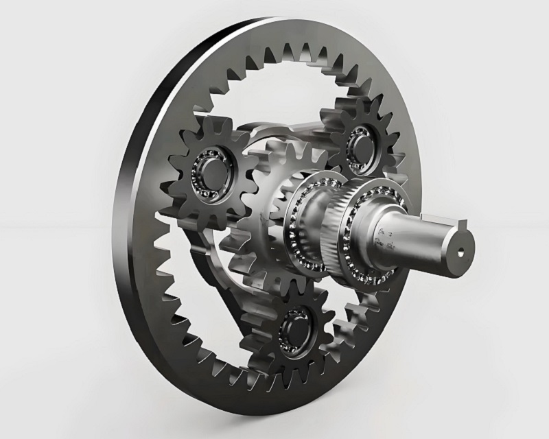
Planetary Gears & Custom Gears
Gear Terminology/Parameter Calculation and Formulas
It is essential to understand gear parameters for designing, selecting and maintaining gear systems, which determines gear performance and its compatibility with other components. For example, the gear module determines the size and strength of the gear teeth.
|
Gear Parameter |
Symbol |
Definition |
Formula |
|
Module |
m |
The ratio of the pitch diameter to the number of teeth |
m = d/z |
|
Pressure Angle |
α |
The angle between the line of action and the line perpendicular to the pitch line |
α = cos⁻¹(Db / Dp) |
|
Number of Teeth |
z |
The number of teeth on the gear |
z = DP x d = π x d/CP |
|
Pitch |
p |
The distance between corresponding points on adjacent teeth |
p = πm |
|
Circular Pitch |
CP |
The distance between corresponding points on adjacent teeth along the pitch circle |
CP = πm |
|
Diametral Pitch |
DP |
The ratio of the number of teeth to the pitch diameter |
DP = 25.4 / m |
|
Tooth Depth |
h |
The total depth of the tooth from the root to the tip |
h = 2.25m (= Addendum + Dedendum) |
|
Addendum |
ha |
The height of the tooth above the pitch circle |
ha = 1.00m |
|
Dedendum |
hf |
The depth of the tooth below the pitch circle |
hf = 1.25m |
|
Tooth Thickness |
s |
The thickness of the tooth at the pitch circle |
s = πm / 2 |
|
Reference/Pitch Diameter |
d |
The diameter of the pitch circle |
d = zm |
|
Tip Diameter |
da |
The diameter at the top of the teeth |
da = d + 2m |
|
Root Diameter |
df |
The diameter at the bottom of the teeth |
df = d – 2.5m |
|
Center Distance |
a |
The distance between the centers of two mating gears |
a = (d₁ + d₂)/2 |
|
Tip and Root Clearance |
c |
The distance between the tip of one gear and the root of the mating gear |
c = 0.25m |
|
Transverse Module |
mt |
The module in the transverse plane |
mt = mn/cos β |
|
Normal Module |
mn |
The module in the normal plane |
mn = m/cos β |
Gear Teeth Profile
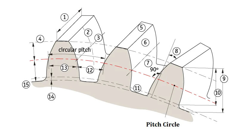
Gear teeth are the individual projections on the circumference of a gear that mesh with corresponding teeth on another gear to transmit motion and power. The gear teeth profile refers to the shape of the gear tooth, which is critical for proper meshing and power transmission. The most common gear teeth profile is the involute profile, which provides smooth and continuous contact between teeth. Other profiles include cycloidal and epicycloidal, but involute is widely used due to its ease of manufacturing and efficient operation.
- Face width: The width of the gear tooth along the direction perpendicular to the axis of rotation.
- Profile line: The outline of the gear tooth on the pitch circle.
- Flank line: The line along the side of the gear tooth.
- Addendum circle: The circle that passes through the tops of the gear teeth.
- Topland: The flat surface on top of the gear tooth between the addendum circles of adjacent teeth.
- Face: The working surface of the gear tooth.
- Flank: The side of the gear tooth.
- Pressure angle: The angle between the line of action and the line perpendicular to the pitch line.
- Whole depth: The total depth of the gear tooth from the root to the tip.
- Tooth or working depth: The depth of engagement between two meshing gears.
- Clearance circle: The circle that represents the clearance between the root of one gear and the tip of the mating gear.
- Slot width: The width of the space between adjacent teeth on the gear.
- Tooth thickness: The thickness of the gear tooth at the pitch circle.
- Clearance: The distance between the tip of one gear and the root of the mating gear.
- Dedendum circle: The circle that passes through the bottoms of the gear teeth.
Types of Gear Trains
A gear train is a mechanical system consisting of a series of interconnected gears that work together to transmit rotational motion and torque from one component to another. It is widely used in machinery, vehicles, and devices to achieve changes in speed, torque, direction, or axis of rotation.
1. Simple Gear Train
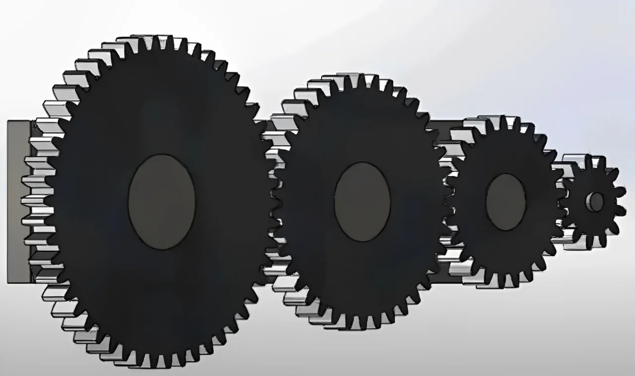
A simple gear train consists of two or more gears connected in series along parallel shafts, with each gear mounted on its own shaft. The axes of the shafts are parallel, and the gears mesh with each other to transmit motion and power. The first gear is called the driver gear, and the second gear is the driven gear. The gear ratio, which determines the speed and torque relationship between the driver and driven gears, is calculated based on the sizes of the gears. If there are intermediate gears, the number of teeth on the intermediate gears does not affect the gear ratio, but can change the direction of rotation. For example, if the number of intermediate gears is odd, the driver and driven gears rotate in the same direction; if even, they rotate in opposite directions.
2. Compound Gear Train
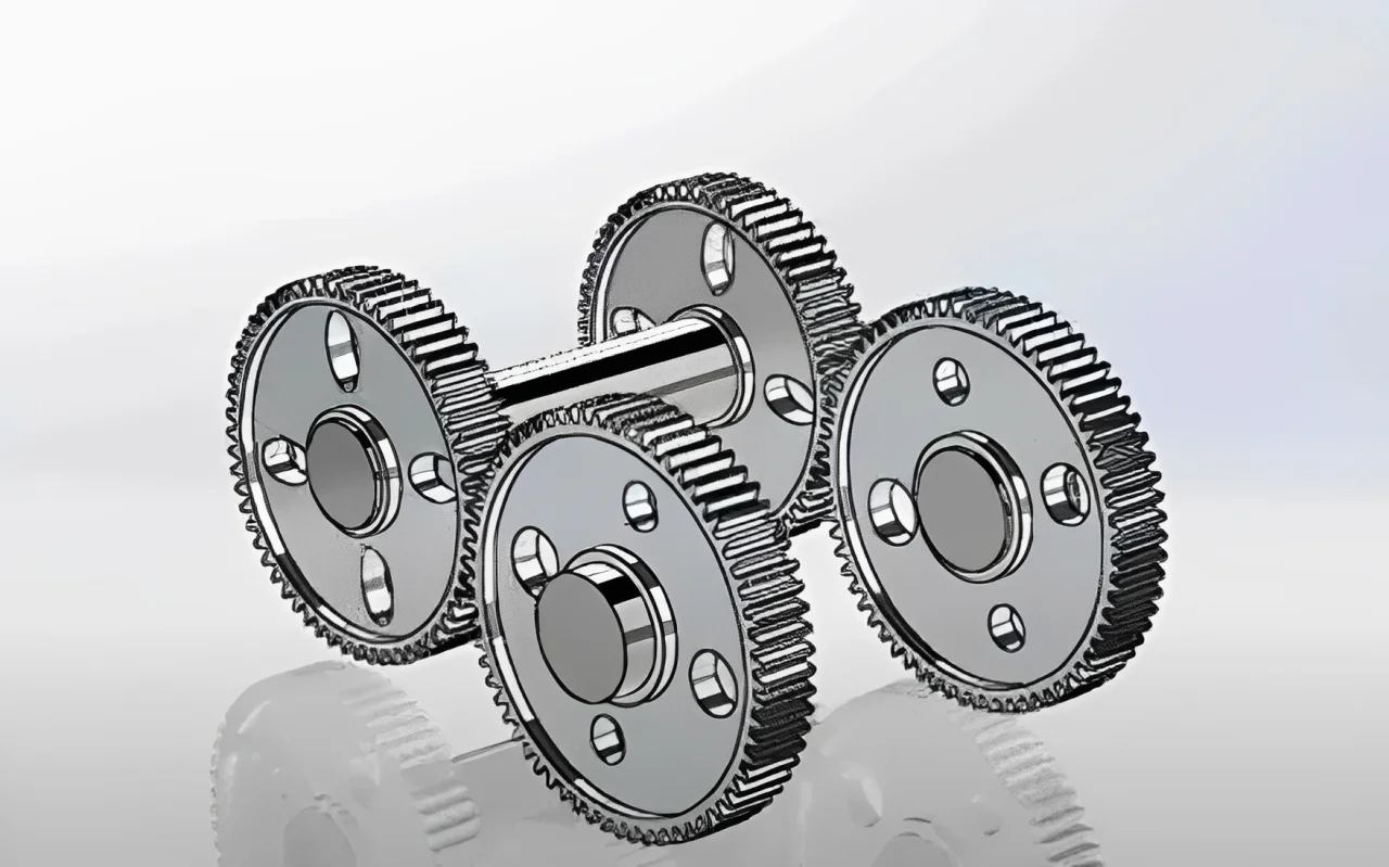
A compound gear train features multiple gears mounted on the same shaft. By combining multiple gears on a common shaft, a wider range of speed and torque ratios can be achieved, enhancing versatility. It can provide more gear ratios and greater torque multiplication compared to a simple gear train. However, it is more complex in structure, with higher manufacturing costs and potential for increased friction and wear. Compound gear trains are commonly used in automotive transmissions, machine tools, conveyor systems, and other mechanical systems requiring a wide range of speed and torque adjustments.
3. Reverted Gear Train
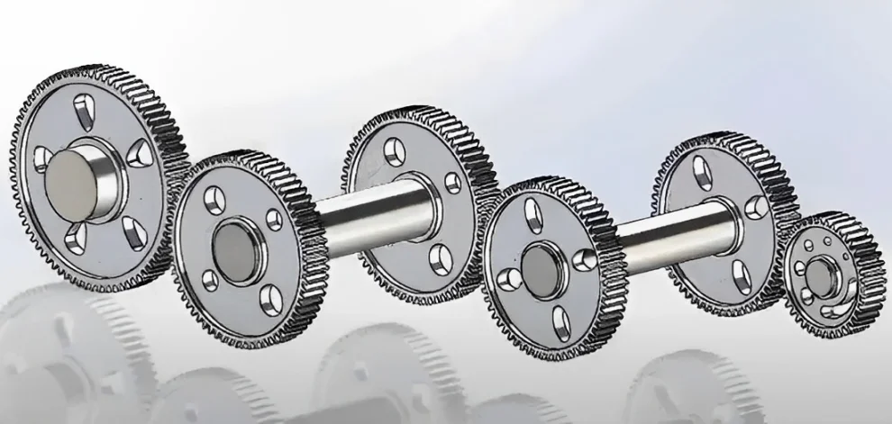
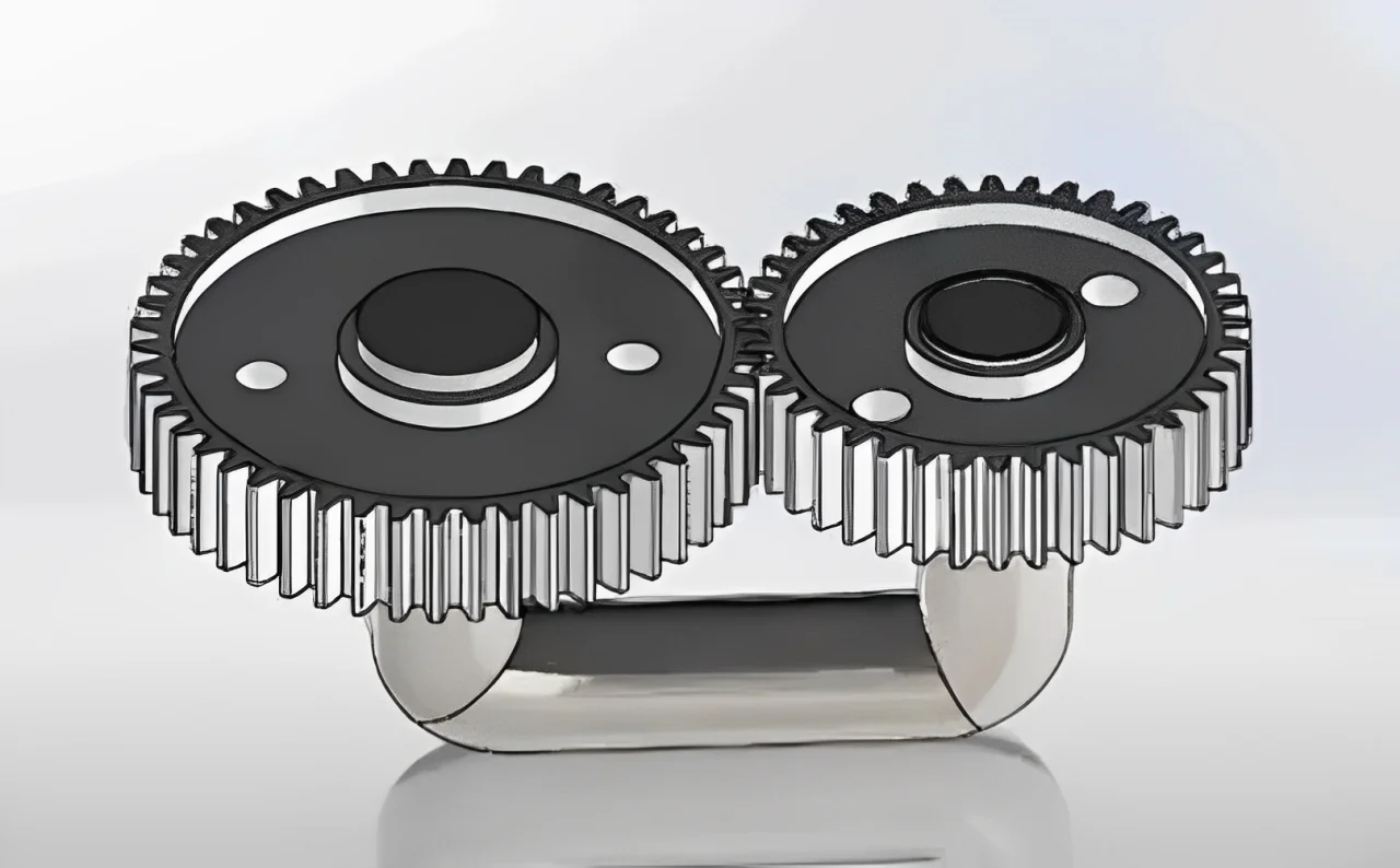
A reverted gear train is a special type of compound gear train where the axes of the first and last gears coincide. Typically, two gears are mounted on parallel shafts, and a third gear serves as an idler or intermediate gear connecting them. The first and last gears share a common axis, and the idler gear meshes with both the driver and driven gears. This arrangement causes the first and last gears to rotate in opposite directions. Its main advantage is the ability to reverse the direction of rotation, which is often necessary in certain industrial processes. Additionally, its compact design makes it space-efficient. Common applications include printing presses and textile machinery. For instance, in printing presses, it can change the direction of paper feed to enable continuous printing on both sides of the paper without stopping.
4. Epicyclic Gear Train
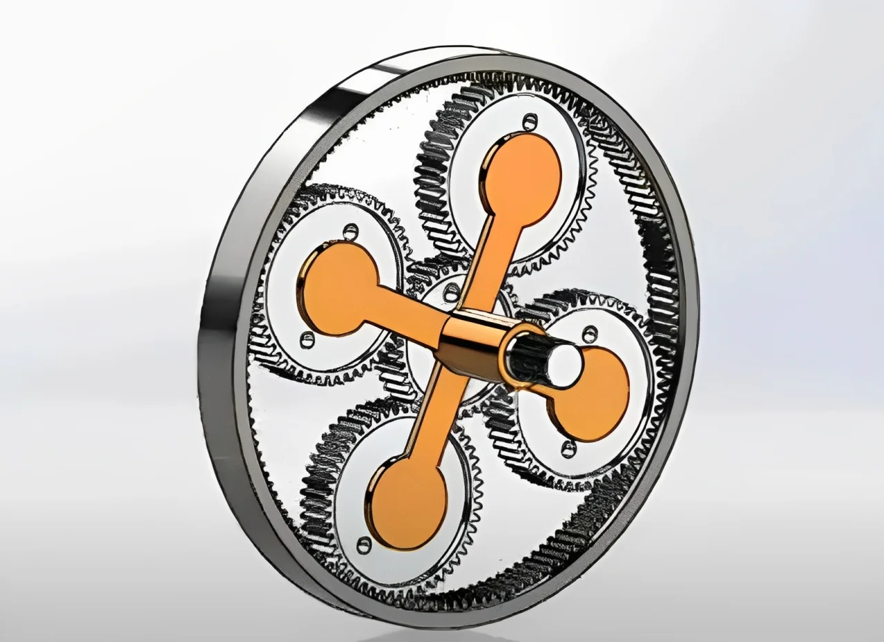
An epicyclic gear train, also known as a planetary gear train, is a complex and versatile gear arrangement. It typically consists of a central sun gear, a planet carrier holding one or more planet gears, and an outer ring gear. The planet gears mesh with both the sun gear and the ring gear, allowing them to rotate on their own axes while orbiting around the sun gear. Power can be input, output, or controlled through any of these components, enabling a wide range of applications and motion patterns. Its advantages include compactness, versatility in controlling rotational motion, and load distribution through multiple planet gears, which reduces wear and increases durability. However, it is more complex to design, manufacture, and maintain, with potential energy losses due to friction and wear. Common applications include automatic transmissions in vehicles, robotics, aerospace systems, and industrial machinery.
5. Sun and Planet Gear Train
The sun and planet gear train is a type of planetary gear train, primarily consisting of a sun gear and one or more planet gears. The planet gears mesh with the sun gear and rotate around it. Unlike the reverted gear train, the sun and planet gear train does not require the axes of the first and last gears to coincide. Its structure is relatively simple, and it can achieve a certain gear ratio and motion transmission. It is commonly used in some early mechanical clocks and simple mechanical devices.
Gear Ratio
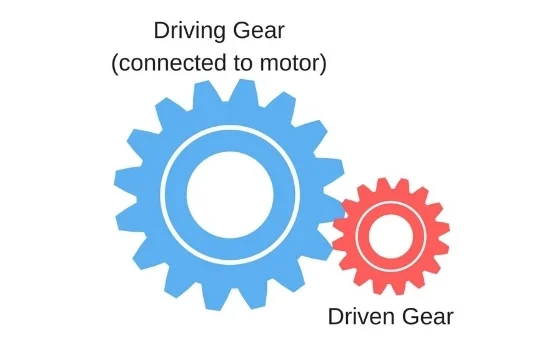
The gear ratio is the ratio of the number of teeth on the driven gear to the number of teeth on the driving gear. It can also be expressed as the ratio of the rotational speed of the driving gear to the rotational speed of the driven gear. The gear ratio determines the mechanical advantage and torque transmission between two meshing gears.
Gear Applications – Industries Our Gear Manufacturing Served
Junying has experience supporting a wide range of industries with precision gear manufacturing and CNC machining services. Our gears power automotive drive systems, improve efficiency in industrial equipment, and help deliver accuracy in medical devices. From aerospace assemblies to marine propulsion, clients trust us to meet demanding standards across various fields. We have partnered with electronics manufacturers for miniature gears, assisted agricultural equipment builders with durable solutions, and produced components for high-tech machinery worldwide. Learn more about the industries that rely on our expertise and see how our manufacturing can support your business goals.
- Automotive
- Aerospace
- Medical Devices
- Industrial Machinery
- Marine
- Electronics
- Military
- More
Custom Gear Manufacturing & Fabrication FAQs
What materials can you use for custom gears?
We machine gears from steel, stainless steel, aluminum, brass, titanium, plastics (nylon, POM, PEEK, etc.).
Can you provide prototypes and small batches?
Yes, we offer rapid prototyping and flexible production to accelerate your development cycle.
How do you ensure gear quality?
Our process includes strict dimensional inspection and surface finish checks for every custom gear before shipping.

