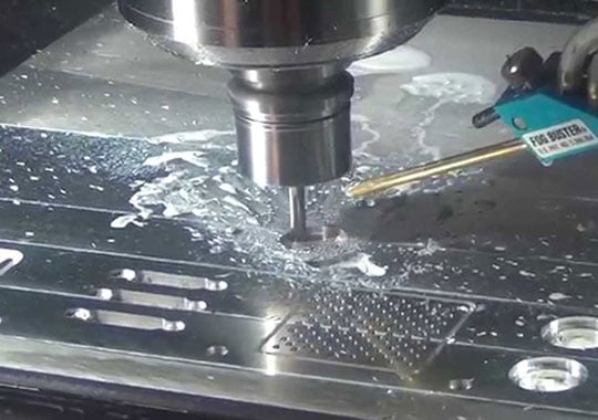
Milling Speed And Feed Calculator – Mill Calculator for RPM, IPM, SFM and More
How to calculate CNC milling speeds and feeds? Even if you know the milling speed and feed formulas, it still takes a lot of time to work out the results, especially when there are multiple cutting tools to select. Fast to determine cutting/spindle speed (RPM) and feed rate (IPM) for the different milling operations and tools using the Milling Speed and Feed Calculator, which saves time greatly and avoid mistakes during the calculation. You can also figure out the cut time in minutes based on the cut length and feed rate. Welcome to use Turning Speed and Feed Calculator and Drilling Speed and Feed Calculator at CNCLATHING.COM as well.
Note:
- The RPM calculated in the Mill Speeds and Feeds Calculator refers to the spindle speed in milling process, and IPM refers to feed rate.
- The exact RPM is not always needed, the following calculator (formula) may be used to estimate the value closely.
- Cutting speed (SFM): the rate at the workpiece surface, irrespective of the machining operation used.
- Tool diameter and Cut length in this calculator in inches.
- Milling RPM and IPM calculations use the desired tool diameter, number of teeth, cutting speed, and cutting feed, which should be chosen based on the specific cutting conditions, including the workpiece material and tool material.
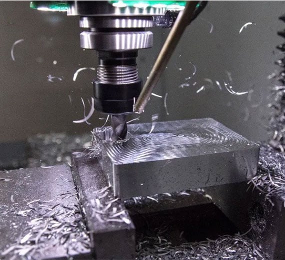
Milling Speed and Feed Calculator
|
||||||||||||||||||||||||||||||
 |
What Is Cutting Speed in Milling – Milling Speeds (RPM & SFM) Formula
CNC milling speeds and feeds are two important velocities for the machining process: cutting speed and feed rate. Cutting speed refers to how fast the cutting edge of the milling tool moves as it rotates. It is usually measured in two common ways:
Revolutions Per Minute (RPM): This is the number of full rotations the milling cutter makes in one minute. It tells you how fast the tool spindle is spinning around its axis. RPM stays constant during a milling operation.
Milling RPM Calculation Formula: RPM = SFM x 12 / π x Tool Diameter or SFM x 3.82 / Tool Diameter (Another version is RPM = Surface Meter Per Minute x 318.06 / Tool Diameter)
Surface Feet Per Minute (SFM): This measures the actual speed of the cutter’s edge against the material surface. It depends on both the RPM and the diameter of the tool. Since a larger diameter tool covers more distance per rotation, it has a higher surface speed even at the same RPM. SFM is a constant, while RPM is a variable based on the tool diameter.
Milling SFM Calculation Formula: SFM = RPM x π x Tool Diameter / 12
What Is Feed Rate in Milling – Milling Feeds (IPM & IPT) Formula
Milling feed refers to the speed at which the cutter moves along the workpiece, essentially how fast the tool advances through the material. Feed rate can be measured in IPM and IPT. Feed rate affects the quality of the cut, tool wear, and machining efficiency. If the feed is too slow, the tool rubs more than cuts, generating heat and wearing faster. If too fast, it overloads the tool and can cause breakage or poor finish. CNC milling feed depends on multiple factors such as tool material, workpiece hardness, cut size, cutter type and size, surface finish requirements, machine power, and overall setup rigidity. Importantly, the principle is to use the highest feed rate that conditions allow because very low feeds (below 0.001 inch per tooth) tend to reduce tool life unless small-diameter end mills are used on hard materials.
Inches Per Minute (IPM): The distance the tool moves forward every minute.
Milling IPM Calculation Formula: IPM = RPM x IPT x Number of Flutes / Teeth
Inches Per Tooth (IPT) or Chip Load: The distance the tool moves forward for each tooth on the cutter per revolution. This is often preferred because it relates directly to the load on each cutting edge.
Milling IPT Calculation Formula: IPT = IPM / RPM x Number of Flutes
How to Calculate Speeds and Feeds in Milling?
Step 1: Identify the Machining Operation and Materials
Begin by determining the type of milling operation you’re performing, such as face milling or slot milling, as well as the material you are cutting and the type of cutting tool material. These factors influence the recommended cutting parameters and help you select the proper data for calculations.
Step 2: Find the Recommended Surface Feet Per Minute (SFM or SFPM)
Next, consult reliable references like the Machinery’s Handbook or the tool manufacturer’s technical data sheets to find the recommended SFM for your tool and workpiece combination. This value represents the ideal speed at which the cutting edge should move relative to the material surface.
Step 3: Calculate the Spindle Speed (RPM)
To calculate the spindle speed in revolutions per minute (RPM), use the formula: RPM = SFM x 3.82/ Tool Diameter. Here, multiply the selected SFM by 3.82 (a constant to convert feet per minute to inches per minute and account for circumference) and divide by the tool diameter in inches. This gives the RPM setting that will achieve the desired surface footage, adjusting for the size of your cutter.
Example 1: Face Milling 1040 Carbon Steel with a 2-inch Face Mill
Tool diameter: 2 inches
Recommended SFM: 300 feet/min (starting point)
Calculate RPM: RPM = 300 x 3.82 / 2 = 573 RPM
Step 4: Determine the Chip Load (Feed per Tooth)
After calculating RPM, find the recommended chip load, the amount of material each tooth removes per revolution. This value usually comes as a range, and you can select a starting point within that range based on your application.
Step 5: Calculate the Feed Rate
Calculate the feed rate (in inches per minute) by multiplying the spindle speed (RPM) by the number of teeth on the cutter and the chip load: Feed Rate = RPM x Number of Teeth x Chip Load. This formula determines how fast the tool should feed into the material to maintain optimal cutting conditions and tool life.
Example 2: Continuing with the 2-inch Face Mill
RPM: 573 (from above)
Number of teeth: 5
Chip load: 0.003 inches/tooth (starting point)
Calculate feed rate: Feed Rate = 573 x 5 x 0.003 = 8.59 inches/min
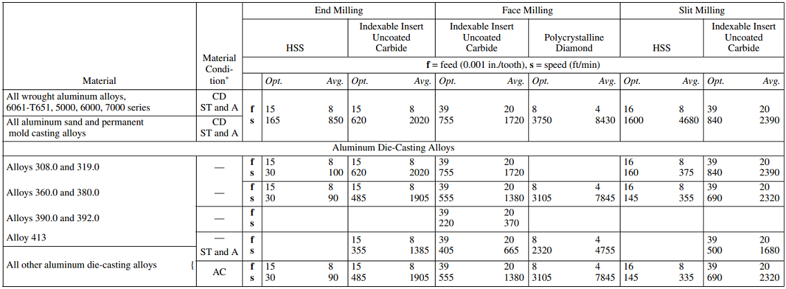
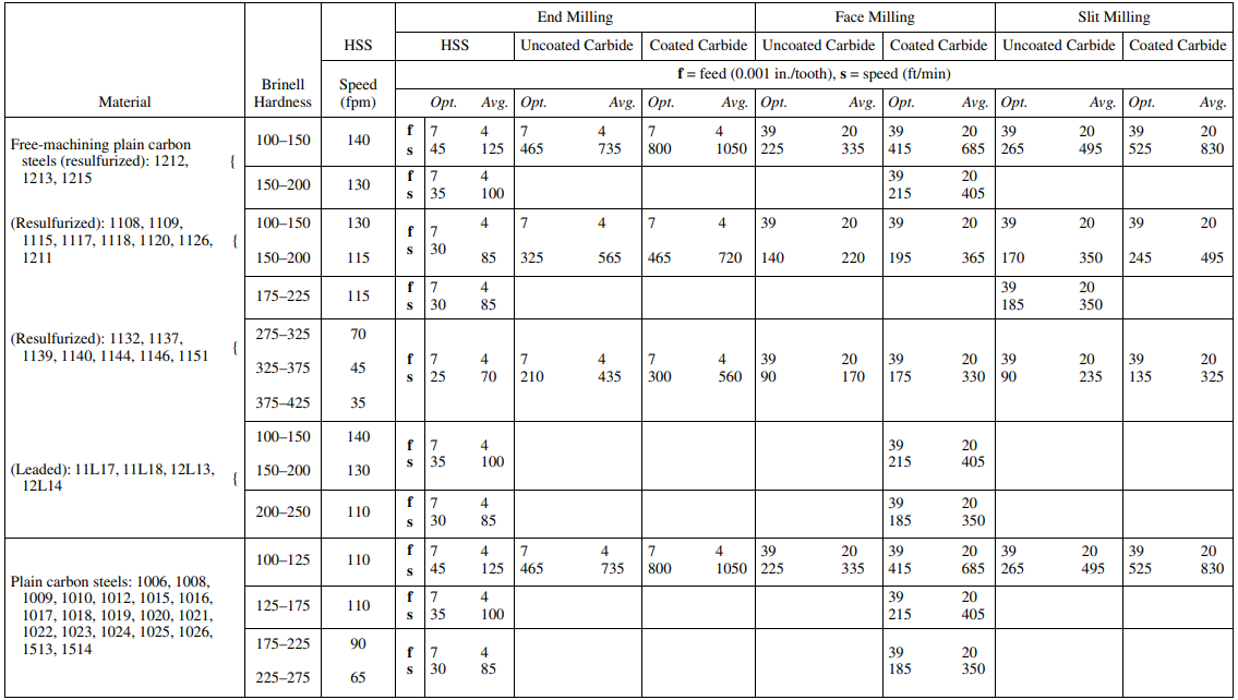
Milling Speeds and Feeds Chart for Different Alloys
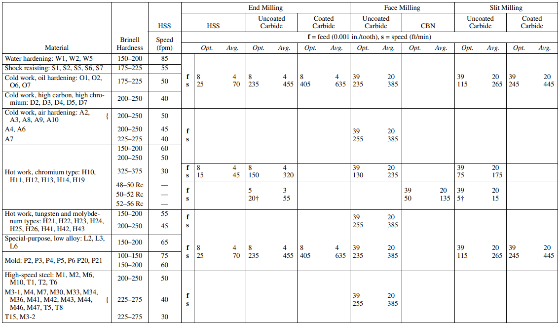
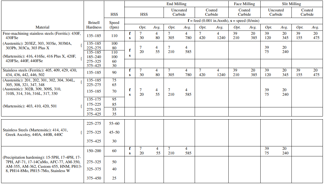
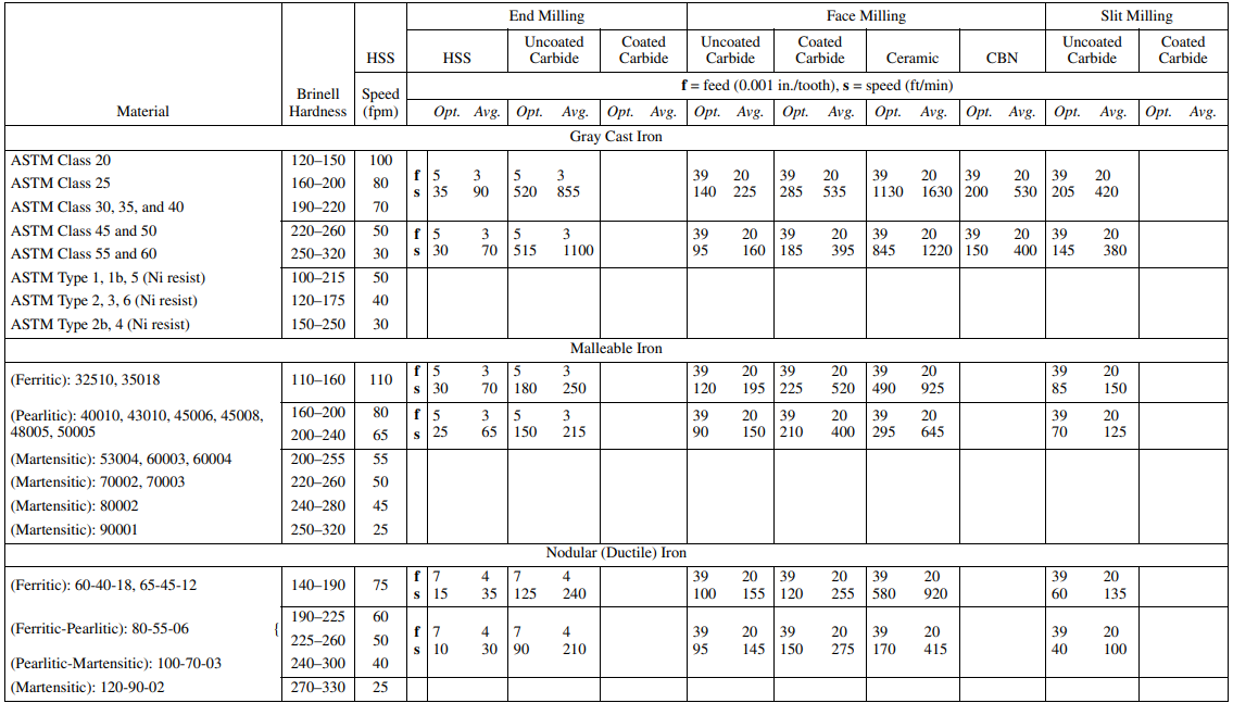
If you have no exact data to calculate but want to know the recommended RPM for stainless steel or other materials, you can also check out these charts features cutting speeds and feeds used in CNC milling.
Note:
The milling speed and feed tables provide detailed guidelines for selecting appropriate values when milling various materials, including aluminum alloys and steels.
- End Milling data is based on a 3-tooth tool with a 20-degree helix angle, 1-inch diameter, and specified axial and radial depths of cut. These speeds apply universally across tool diameters.
- Face Milling data assumes a 10-tooth, 8-inch diameter face mill operating with a 15-degree lead angle and specific depth and width of cut, with the cutter axis positioned close to the workpiece center line. If the cutter offset from center increases significantly, speed adjustments used for end and side milling should be applied instead. For face milling, heavier feeds are suited primarily for larger cutters on machines with sufficient power. Smaller cutters should start with lower feeds and increase feed as performance indicates.
- Slit and Slot Milling speeds are based on an 8-tooth cutter with a 10-degree helix angle and specific cutter width and depth of cut.
Material hardness strongly influences feed rate choices: harder alloys require slower feeds, while softer materials can tolerate higher feeds. Wider and deeper cuts also necessitate slower feeds to maintain tool life and surface finish. For example, when milling magnesium, faster feeds are recommended to produce thicker chips and reduce the risk of spontaneous combustion caused by fine chips. Milling stainless steel requires feeds high enough to cut through the work-hardened surface layer produced by previous cutting edges.
When planning milling operations with high speeds and feeds, it is critical to verify the machine’s power capacity can handle the required metal removal rate, especially when using carbide cutters capable of high material removal rates. If power capacity is exceeded, reducing cutting speed is preferable to reducing feed per tooth.
Abbreviations in the Chart
- A: Annealed
- AC: As Cast)
- CD: Cold Drawn)
- ST and A: Solution Treated and Aged
Cutting Speeds and Feeds Chart for Milling Aluminum
Cutting Speeds and Feeds Chart for Milling Plain Carbon and Alloy Steel
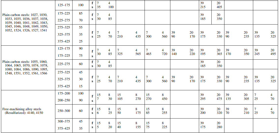
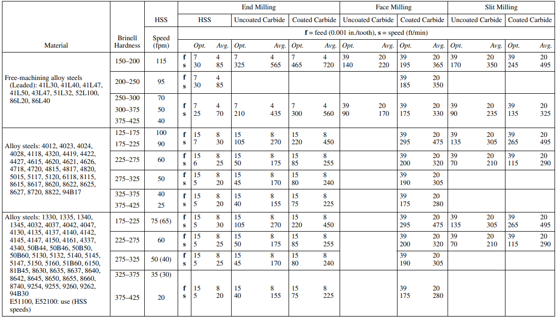

Cutting Speeds and Feeds Chart for Milling Tool Steel
Cutting Speeds and Feeds Chart for Milling Stainless Steel
Cutting Speeds and Feeds Chart for Milling Ferrous Cast Metal

The Importance of Milling Speed and Feed Calculations
The spindle speed is derived from cutting feeds and speeds, it is one of the ideal cutting conditions for a tool, if the condition is not ideal, the adjustment of spindle speed is necessary, usually reduce in RPM or modify it to a correct value. Some materials can be cut at a wide range of spindle speeds, while cutting speed is critical to some materials like stainless steel, it’s easy to harden under cold working, then resist the tool’s cutting action. When determining which feed rate to use, the calculation for milling is a little more complicated, because the operation on milling machine involves multi-tipped/multi-fluted cutting tools, then the desired milling feed rate becomes dependent on the number of teeth on the cutter, and the desired amount of material per tooth to cut. Insufficient feed rate or incorrect spindle speed will cause improper cutting conditions, therefore it’s important to figure out the CNC milling speed and feed with our Milling spindle speed and feed rate calculator and control it carefully to avoid overheating of the cutter and workpiece.
Learn about our CNC milling services or require custom milling parts quotation, please feel free to contact us through the email [email protected].
