- Home
- Machining techniques
- CNC Machining Services
- Cooperative supply services
- Designs
- Materials
- Finishing Services
- Shop
- Products
- Guide
- About Us
- Contact Us
2021.5.21
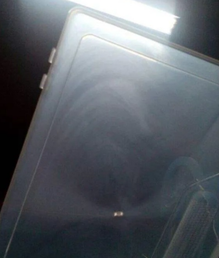
When the depth of the gate is much smaller than that of the cavity entrance, and the filling rate is very high, the melt flow becomes unstable jet flow, the front jet has solidified, and the back flowing melt fills the cavity, and the serpentine flow pattern will appear on the surface of the product.
Solutions:
– Change the process conditions. By reducing the injection rate, the jet effect will be gradually eliminated, and the melt flow mode will be expanded, and the expanded flow will make the product have better surface quality. In addition, increasing the mold temperature and melt temperature will also reduce the jet effect and expand the melt flow.
– Change the mold gate size. When the gate depth is a little smaller than the cavity depth, the jet expansion makes the melt behind merge with the front edge of the jet not far away from the front, so that the jet effect is not obvious. When the gate depth is equal to or close to the cavity depth, the mold filling rate is low and the spreading flow is formed.
– Change the mold gate angle. The angle between the mold gate and the moving mold is 4O ~ 5O, so that when the melt flows out from the gate, it will be stopped by the mold cavity wall first, which can prevent the appearance of snake flow.
– Change the mold gate position. When the mold gate is set at the nearest position to the mold cavity wall (perpendicular to the direction of the gate), when the melt flows out from the gate, it will be stopped by the mold cavity wall first, which can also prevent the emergence of jet flow and make it become extended flow, so as to avoid the appearance of snake flow line.
In the process of melt filling, the new melt flow is continuously pressed out from the inner layer, which drives the front wave to stagnate and move. At the same time, the front wave edge is constantly stretched. Due to the flow resistance, the later melt pressure rises and the front wave is flattened, resulting in stagnant accumulation and the formation of product surface waviness. Especially in the case of high injection rate, low injection pressure or unreasonable mold structure, the melt flow in and out, and PP crystallization in and out, it is more likely to cause the surface crystallinity of the product is inconsistent, forming wavy lines on the surface of the product.

Solutions:
– Change the process conditions. High pressure and low speed injection can keep the stability of melt flow and prevent wavy lines.
– Increase the mold temperature. With the increase of mold temperature, the melt fluidity increases. For crystalline polymer, higher temperature is conducive to the uniformity of crystallization, so as to reduce the appearance of waviness.
– Change the cavity structure. The structure of the mold can also cause wavy lines on the surface of the product. If the edges and corners of the mold core are prominent, the melt flow resistance is large, which will cause the instability of the melt flow and form wavy lines. Therefore, changing the edges and corners of the mold core to make it buffer transition and keep the melt flow stable can prevent the occurrence of wavy lines.
– Change the thickness of the product. The uneven thickness of the product will make the melt flow resistance larger and smaller, resulting in unstable melt flow. Therefore, the uniform thickness of the injection mold product can also prevent the appearance of wavy lines.
When the injection rate is too high and the melt is ejected, because of the elasticity of the melt, when the melt flows rapidly from the barrel through the mold gate to the mold cavity, the elastic recovery of the melt is too fast, resulting in the melt fracture and radiation.
Solutions:
– Change the process conditions. High pressure and low speed injection can increase the flow time of the elastic melt in the same flow length, increase the degree of elastic failure, and reduce the occurrence of radiation.
– Change the mold gate shape. By increasing the gate or changing the gate to fan-shaped, the elasticity of the melt can be slightly restored before it enters the mold cavity to avoid melt fracture.
– Lengthen the main runner length of the mold. Before the melt enters the mold cavity, the elastic failure of the melt can be avoided. (4) replace the equipment with extended nozzle. Lengthening the flow path of the melt before the mold cavity can increase the degree of elastic failure of the melt and avoid the occurrence of radiation lines due to the melt fracture.
When the melt flows in the mold cavity, one end of the molecular chain near the solidification layer is fixed on the solidification layer, and the other end is stretched along the flow direction by the adjacent molecular chain. Because the flow resistance of the melt near the cavity wall is the largest and the flow rate is the smallest, while the flow resistance at the center of the cavity is the smallest and the flow rate is the largest, so the velocity gradient is formed in the flow direction. Therefore, when the injection rate is small, the injection pressure is high or the thickness of the product is thin, the shear force of the melt near the cavity wall is the strongest and the orientation degree is the largest, The polymer shows internal stress when it is stretched in the flow, which leads to the appearance of fluorescent lines on the surface of the product.
Solutions:
– Change the process conditions. With the increase of injection rate, the cooling time of the melt in the same flow length decreases, the solidification of the melt per unit volume is relatively slow, the internal stress of the product is weakened, and the appearance of fluorescent lines on the surface of the product is reduced.
– Increase the mold temperature. Compared with the mold temperature, the relaxation of macromolecules is accelerated, the molecular orientation and internal stress are reduced, thus reducing the appearance of fluorescent lines on the surface of products.
– Change the cavity structure and increase the product thickness. The results show that the thickness of the product is larger, the melt cooling is slower, the stress relaxation time is longer, the orientation stress is reduced, and the fluorescent lines are reduced.
– Heat treatment (oven baking or hot water boiling). The heat treatment makes the macromolecular movement intensified, the relaxation time shortened, and the depolarization effect strengthened, so as to reduce the fluorescence lines.
 Plastic Shrinkage: What Causes Plastic Shrinkage & How To Fix | CNCLATHING
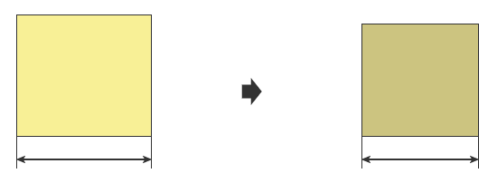 Mold Shrinkage Chart, Formula, Calculation, Plastic Shrinkage Rate | Injection Molding Shrinkage
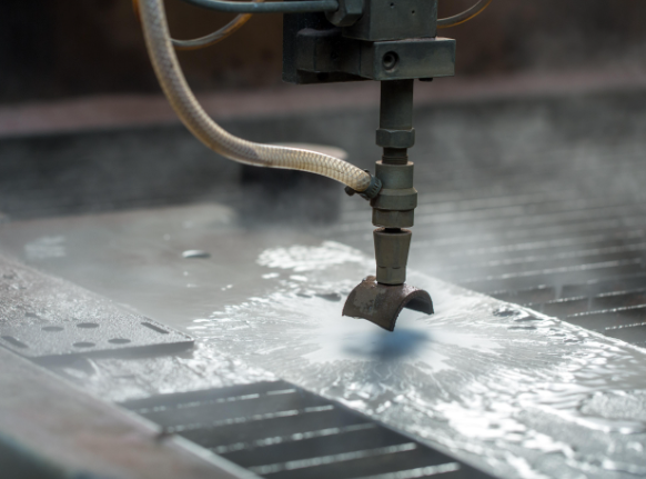 Best Waterjet Machines – How to Choose the Right Waterjet Cutting Machine
 Classification of 8 Common Plastic Molds in CNC Machining
 Injection Molding vs Blow Molding – Difference Between Blow Molding and Injection Molding
 Causes & Solutions To Overflow Of Injection Molding Machine Head | CNCLATHING
