
Besides CNC turning and milling, there are many other operations that can be done on CNC machines for different purposes. What is the facing operation on lathe machines? How to perform facing on a lathe, and what are the differences between facing, turning, and milling? Follow us to go through all these questions and find the answers, and understand more about the facing process.
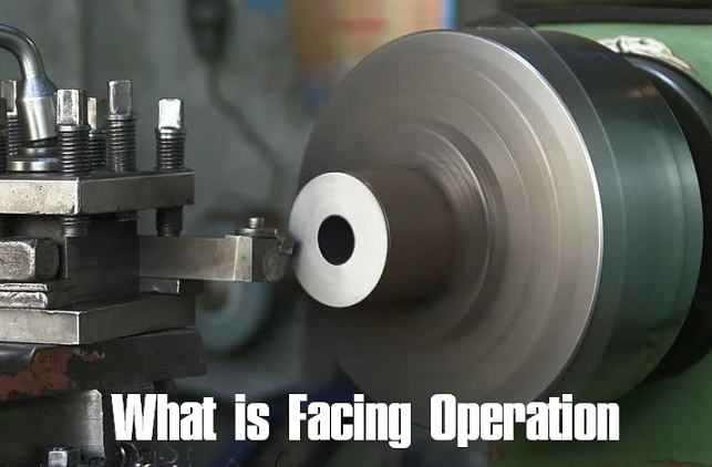
What Is a Facing Operation?
Facing is a machining operation that can be performed on a lathe or a milling machine. The facing process generally removes materials from the end or shoulder of the workpiece. The purpose of facing is to create a flat end face, and it is usually the first operation to do on any part. Facing operation is one of the primary things we can do on the lathe machine when we want to get any shape on a particular part.
Which Type of Surface Is Produced in the Facing Operation?
Whether on a lathe or a milling machine, facing is typically used to remove materials from the block to produce a flat surface.
What Is Spot Facing?
Spot facing is a precise machining operation used to create a smooth, flat, and square surface around the opening of a drilled hole, ensuring a level seating area for washers, nuts, or bolt heads. This process removes any roughness or curvature on the surface immediately surrounding the hole, allowing hardware to sit flush and secure. The tool used for this operation is known as a spot facer or spot-facing tool. While similar to counterboring, which is primarily intended to recess bolt heads below the surface, spot facing focuses specifically on producing a flat, even seat rather than a recessed cavity.
Facing Operation Diagram (3D & 2D Drawing)
Facing Operation on Lathe Machine – How to Perform Facing on a Lathe
The function of facing on a lathe is mainly to reduce the length of the workpiece. How is facing performed on a lathe machine?
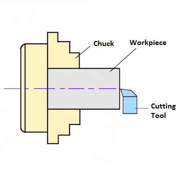
1. Prepare and clamp the workpiece
Begin by securely clamping the raw stock onto the lathe chuck, ensuring it is held firmly in place. Inspect the edges of the workpiece and file off any burrs or protrusions, as raw stock often has uneven surfaces that could cause interrupted cuts or damage the tool during facing. Proper preparation helps achieve a smooth and accurate facing operation.
2. Set up the facing tool correctly
Mount the facing tool onto the quick-change tool post and carefully adjust the tool height so that the cutting edge aligns exactly with the centerline of the workpiece diameter. Incorrect height causes rubbing or damage. Rotate the tool post to establish the proper clearance angle between the tool and workpiece, then lock it in place. This setup prevents tool chatter and ensures a clean cut.
3. Configure the machine settings
Select the appropriate gear ratio to achieve the correct spindle speed based on the material and diameter of the workpiece. The spindle speed influences cutting speed and surface finish quality. Power on the lathe and set the spindle speed accordingly.
4. Position the tool for the facing cut
Use the carriage handwheel to move the tool slowly along the length of the workpiece toward its face, typically by rotating it counterclockwise, and then use the cross slide handwheel to advance the tool toward the diameter of the workpiece. Move the tool carefully until it just contacts the surface, allowing you to hear when cutting begins.
5. Begin cutting the face
Move the tool across the face of the workpiece beyond its outer diameter using the cross slide, then increase the depth of cut progressively by rotating the compound slide handwheel, generally by 0.5 to 1 mm. Slowly feed the tool with the cross slide, maintaining steady movement to ensure a smooth and consistent cut. If the initial pass does not fully engage the surface, retract, increase the depth slightly, and repeat.
6. Manage chip removal during cutting
Pause the feed periodically to allow chips to break off and fall away naturally, preventing accumulation that could damage the workpiece or interfere with the cut. If chips do not clear on their own, stop the machine and safely remove them using long-nose pliers before continuing the operation.
7. Check the finished face and perform finishing cuts
When the tool reaches the center of the workpiece, stop the spindle and inspect the face for flatness and smoothness. If the surface is uneven or rough, perform finishing passes with a smaller depth of cut, about 0.1 to 0.2 mm, adjusting feed rate and spindle speed to improve surface quality. Lower feed rates and higher spindle speeds generally yield better finishes, especially near the center.
8. Considerations for large-diameter workpieces
For large-diameter workpieces, cutting speed varies from the outer diameter to the center since the material speed decreases near the center. To maintain consistent cutting conditions, increase spindle speed when machining smaller diameter zones while keeping the feed rate low and constant.
Precautions
Avoid moving the tool along a freshly cut finishing surface to prevent scratching or damage. Always clear chips before continuing the cut, stopping the machine if necessary to remove them. After reaching the center, retract the tool with the carriage before moving it away with the cross slide, and ensure the tool passes about 1 mm beyond the center to avoid leaving uncut material.
Additional Setup Tips
- Clamp the workpiece as short as possible to reduce overhang, which can cause vibration or bending during facing. Allow about 10 to 20 mm of material protrusion from the chuck jaws for stability.
- Always use the correct cutting speed for the material being machined to optimize quality and efficiency, and consult experienced personnel when working with difficult or unusual materials.
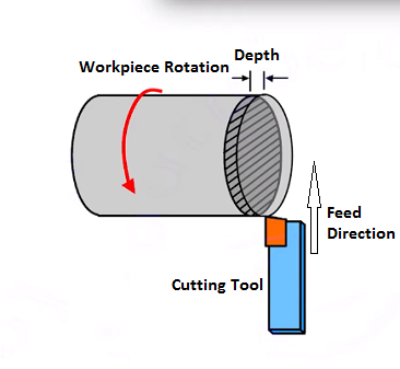
Which type of feed is needed in the facing operation? The cutting tool would be fed in a direction perpendicular to the rotational axis of the piece as it spins in the jaws of the chuck. Facing operation can be performed either by moving the tool from the center away from the workpiece or from the workpiece towards the center. What happens is that the material is removed in the form of chips, and the length of the component is reduced to the desired size. The feed is given with the help of the cross slide in a perpendicular direction to the axis.
Operators can choose to hand-feed the machine or use a power feed; the latter is more ideal when a smoother surface is needed. Speeds and feeds, material hardness, cutter size, clamping types, and more factors will affect the quality and effectiveness of facing on the lathe.
Facing on Milling Machine
Facing operation on milling machines refers to the process of creating a flat surface on a workpiece that is perpendicular to the tool spindle axis. It is a CNC machining objective focused on producing a smooth, even face, often at the end or top surface of the workpiece. While facing describes the goal of the operation, which is making a flat face, face milling is a specific milling method commonly used to achieve this. Face milling involves using a face mill cutter where the primary cutting action occurs on the face of the tool, with the cutter axis perpendicular to the workpiece surface.
Although facing operations on milling machines are often performed by face milling, the two terms are not exactly interchangeable. Facing operation is a broader concept that includes any milling process aimed at producing a flat face, which can also be done using other tools like fly cutters or end mills.
Difference Between Facing, Turning, and Milling Operations
Turning, milling, and facing are all machining operations, but they are performed in a different way with varying machines, cutting tools, direction of tool movement, rotating part, purposes, or types of features or shapes created.
1. Rotation
In turning and facing operations on a lathe, the workpiece rotates around its axis while the cutting tool remains stationary or moves relative to it. Conversely, in milling, the cutting tool rotates instead, and the workpiece is usually fixed or moves slowly. This fundamental distinction defines how material is removed and affects the choice of machine and tooling for each process.
2. Purpose
Turning primarily aims to shape cylindrical parts by reducing or modifying their diameter, creating shafts, rods, and other round components. Facing focuses on producing flat, smooth surfaces, typically to square or finish the ends of parts without changing their diameter, ensuring precise length and surface quality. Milling serves a broader purpose; it produces flat surfaces, slots, complex contours, and diverse geometries beyond simple cylindrical shapes.
3. Tool Movement and Cutting Direction
In turning, the cutting tool moves parallel to the axis of the rotating workpiece to reduce or shape the diameter, producing cylindrical surfaces. In facing, the tool moves perpendicular to the workpiece axis, cutting across the end face to create a flat surface and control length. In milling, the rotating cutter moves along various axes relative to the workpiece, removing material by cutting flat surfaces, slots, or contours, often with multi-axis control.
4. Tool Type and Cutting Action
Both turning and facing use single-point cutting tools that remove material with one cutting edge at a time, suitable for cylindrical shapes and flat end faces, respectively. Milling uses multi-point cutting tools (such as face mills or end mills) with multiple cutting edges, allowing faster material removal and greater versatility in producing complex shapes and flat surfaces on a wide range of workpiece geometries.
Related Articles:
 NPS Thread Dimensions Chart (NPSM & NPSL) | What Is Straight Pipe Thread
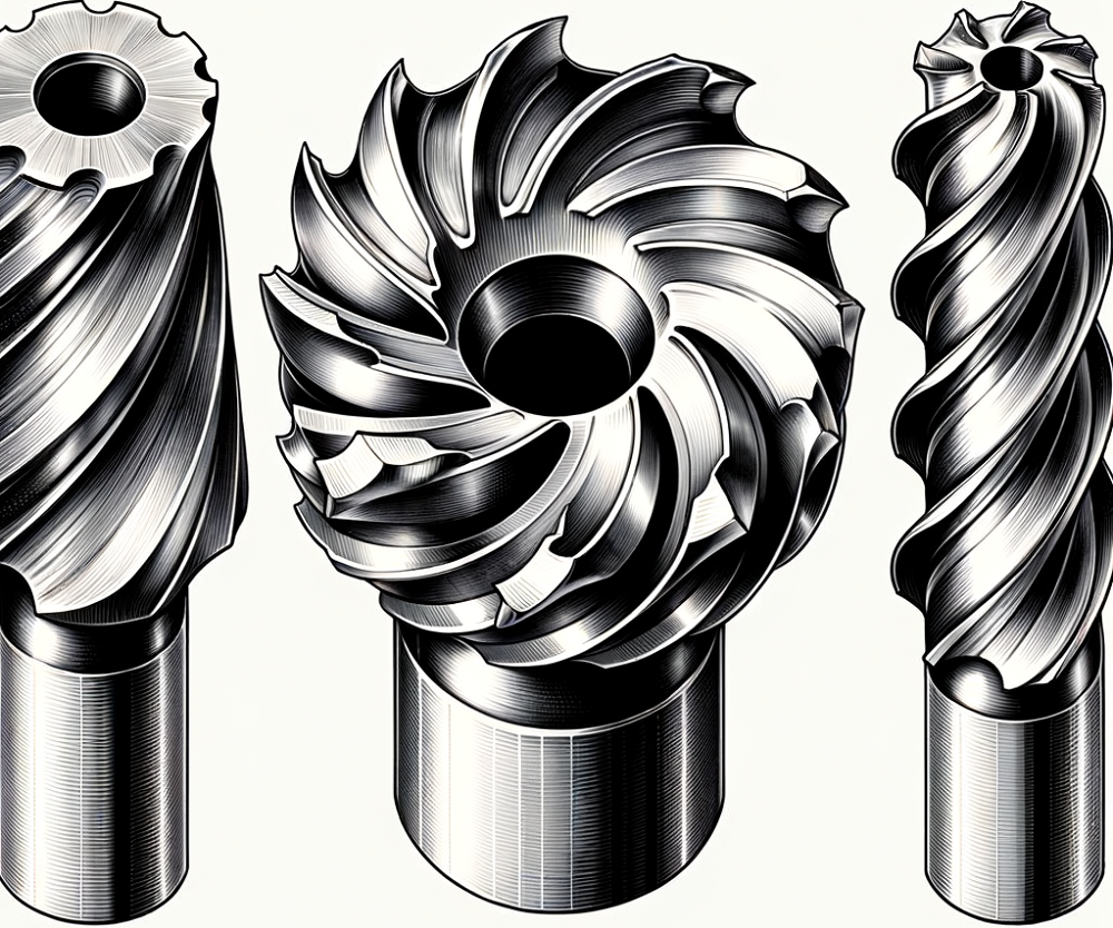 Face Mill vs Shell Mill vs End Mill Cutters: Differences & When To Use Each Milling Cutter?
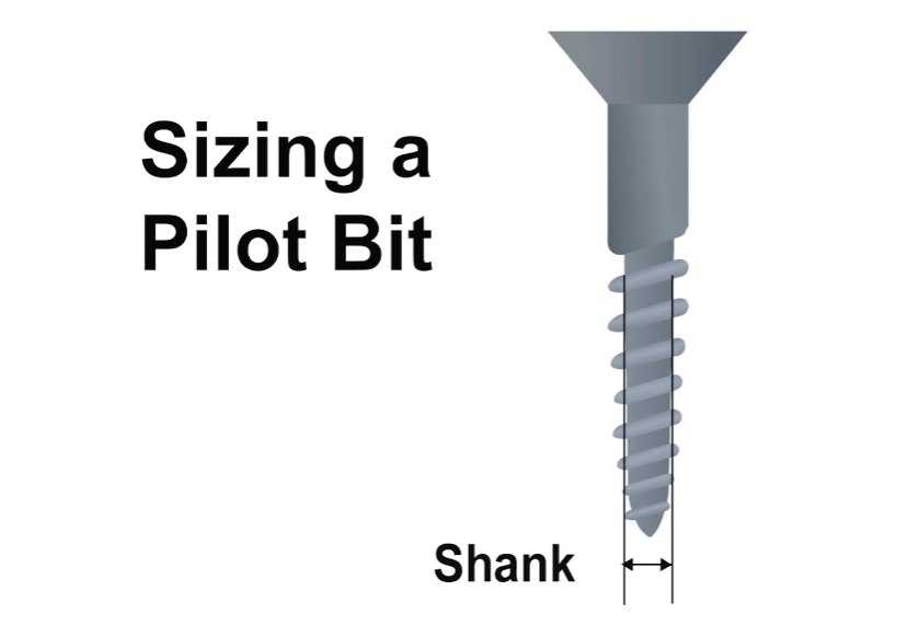 Pilot Hole Drill Bit Size Chart for Wood, Sheet Metal, Lag Screws
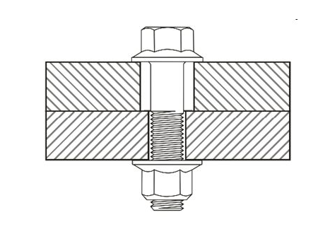 Clearance Hole Size Chart for Metric and Imperial Fasteners (Bolts, Screws & Studs)
 What is Turning in Lathe Machining? Definition, Operation Types, Tools
 Machining Material Density Chart – Density Unit Conversion Table