After the probe is installed on the spindle of the machine tool, use C31 (g31ipf) to perform the movement of the machine tool. Try not to use C00, C01, C02, C03, etc. and fixed cycle procedures to execute the machine tool movement. Only when 631 is used to move the machine tool and collide with the probe rod of the probe, the machine tool will stop moving and will not damage the probe. In the manual or hand pulse motion machine tool, the machine tool will not stop moving or give an alarm when touching the probe rod. Do not touch the probe and various parts to avoid damaging the probe.
1. Calibration of probe
A probe is installed on a machine tool. The machine tool control system does not understand the center deviation value of the probe, the action radius value and the length value of the whole probe. Therefore, it is necessary to calibrate the probe, measure these deviation values and probe length values, and store them in the system macro variable and tool length deviation table respectively. The calibration of probe is divided into three steps: calibration of probe center error, calibration of probe action radius and calibration of probe length. The first two probes can be calibrated by ring gauge, which is a necessary step before using the probe. The correction of probe length is similar to taking the probe as a tool. To measure the tool length compensation value relative to the standard tool or workpiece coordinate system. Therefore, different machined workpieces may have different standard tool or workpiece coordinate systems, and different tool length compensation values relative to the same probe.
To sum up, it is necessary to correct the center and action radius of the probe. After a probe is installed, it only needs to be corrected once, and different workpieces do not need to be corrected again. However, the length of the probe should be corrected differently for different workpieces. When the workpiece measurement macro program and the machine tool processing program are in the same program and share the same workpiece coordinate system, the probe length correction must be carried out first.
Center correction of probe.
Here are work steps:
(1) Edit the calibration center program.
0****. (program number)
C90 C80 C40 C49; (safety protection returns the system to its initial state)
G65 P9021. (spindle orientation and select workpiece probe mode)
C65 P9016 D50. 0. (measurement procedure, the diameter of the inner hole of the ring gauge is about 50mm)
M30. (program completed)
(2) Mechanical correction of ring gauge.
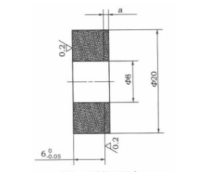
Find a high-precision ring gauge (the diameter of the inner hole of the ring gauge must be within φ Above 25, preferably φ About 50, ring gauge thickness more than 15mm). Fix the ring gauge on the workbench and move the machine so that the concentricity between the central axis of the inner hole of the ring gauge and the rotation axis of the spindle is within 2 μ Within M. Store the machine tool mechanical coordinates with good concentricity in any coordinate system in the workpiece coordinate system deviation table of the control system (to avoid losing coordinates when moving the machine).
After the machine tool has found the position of concentricity, move the Z axis of the machine tool with the probe installed (the x.y axis cannot move), move the probe to 6mm below the top surface of the ring gauge, and pay attention not to touch the object.
(3) Run the calibration center program.
Execute the above program. After completion, the control system obtains the concentricity error between the center of the probe and the spindle axis and stores it in the macro variables #504 (deviation in X direction), #505 (deviation in Y direction). In this way, the center correction of the probe is completed. Do not move the position of the X and Y axes of the machine tool, and then correct the action radius of the probe of the probe.
Correction of the action radius of the probe of the probe.
(1) Edit the correction radius procedure.
(2) Operation of ring gauge. The operation of the ring gauge is the same as that of the center correction of the previous probe.
(3) Run the calibration radius procedure. Execute the program programmed above. After the completion, the control system obtains the action radius values of the probe in four directions and stores them in the macro variable #500 (+ X direction)# 501 (- X direction), #502 (+ Y direction), #503 (- Y direction). This completes the correction of the action radius of the probe.
2. Length correction of probe.
– Edit the calibration probe length program.
– Manual operation. Input the length difference (approximate estimated value) of the probe relative to the Z coordinate of the workpiece coordinate system into the selected length compensation value.
– Run the length correction program. After executing the length correction program, the control system calculates the length compensation error value (the difference between the estimated length deviation and the actual length deviation) and stores it in the wear under the deviation number hi. This completes the probe length correction.
 Method For Measuring Trigger Probe In 5 Axis Machining | CNCLATHING
 Probe Selection Guide & Tips – How To Choose Probe For CNC Machine
 Why Do You Install Probe On CNC Machine – Function & Effect, Advantages Of Probe Installation
 What is Tool Setter – CNC Tool Setter Types, Cost, Work Principle & How To Use
 Control Method Of Workpiece Thickness Of Grating Ruler And Tool Setter
 Development Of On-Line Measurement In Wire EDM Machining
