Control Method Of Workpiece Thickness Of Grating Ruler And Tool Setter

2021.12.28

In the field of textile machinery, it is necessary to use ceramic parts with very smooth surface quality as guide wires. In the process of grinding and thinning of traditional ceramic blanks, it is necessary to manually remove the workpiece and measure its thickness. In the process of achieving the required dimensional tolerance, each workpiece often needs 2 ~ 3 repeated measurements, and the efficiency is low.

In order to improve the machining efficiency, it is necessary to solve the problem of automatic control of machining size. At present, there are many thickness detection methods, such as electromagnetic detection, acoustic emission sensor and laser rangefinder. However, the above methods can only detect metal parts or impact resistance, poor vibration ability, low detection accuracy and high equipment cost. It is difficult to use this kind of grinder at present. Therefore, it is of great significance to find a relatively simple, practical and accurate automatic detection and control method.


Common Methods Of Workpiece Size Measurement

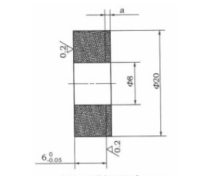
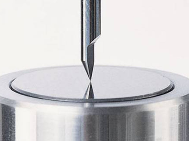
There are many sizes and specifications of ceramic workpieces, and the accuracy level required by various workpieces is also high. This paper takes the workpiece shown in Figure 1 as an example, and a in the figure is the thinning size required in the grinding process. The methods of measuring dimensions can be divided into direct measurement method and indirect measurement method.


1. Direct measurement method

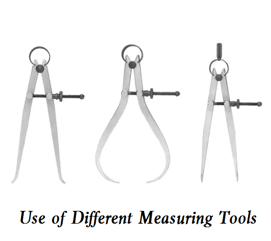
(1) Manual off-line measurement, manually remove the workpiece and measure the size of the workpiece. In the process of mass production, repeated processing and testing result in high labor intensity.

(2) On line active measuring device for grinding machine. The device can only measure the outer circle of the workpiece and obtain the diameter dimension data of the workpiece, but can not obtain the thickness dimension of the workpiece, and can not solve the problem of on-line detection and real-time display of the thickness dimension of the workpiece.


2. Indirect measurement method

The thickness dimension of the workpiece can also be obtained indirectly by detecting the relative distance between the detection element and the machined surface of the workpiece. The methods that can realize indirect measurement mainly include the following:
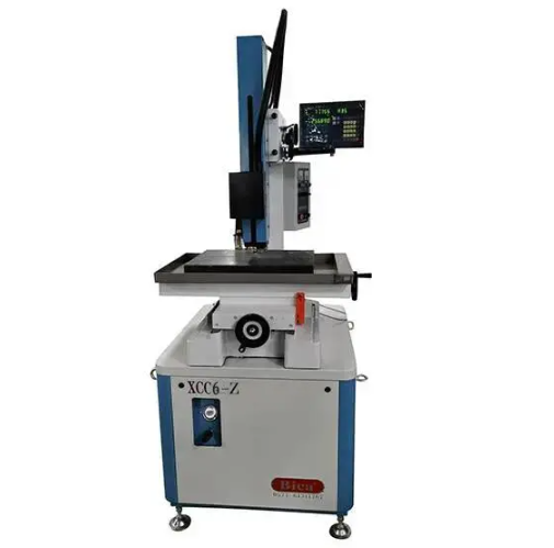
 

(1) Automatic probe

Automatic probe is often used in workpiece size detection of CNC machine. This type of probe has the advantages of high detection accuracy, but the disadvantage is that it needs to be used in the shutdown state. This type of probe is not suitable for batch automatic thinning.


(2) Laser ranging sensor

Laser ranging sensor is used in product thickness detection, relative distance detection and other occasions, and its accuracy can reach 7 μ m、20 μ m、40 μ M et al. The utility model has the advantages of high measurement accuracy, large measuring range, small volume, convenient installation and commissioning, on-line continuous measurement, etc.


(3) Other methods

In addition to the above common ranging methods, there are ultrasonic testing method, magnetic thickness measurement method, eddy current thickness measurement method, electrolytic thickness measurement method, etc. Among the above common methods 7 μ M-class laser ranging sensor can achieve the required accuracy. However, the vibration resistance of the detection element is poor, and the on-line detection without shutdown requires very high rigidity of the machine base. If the intermediate shutdown detection reduces the machining efficiency, and the existence of cutting fluid also affects the detection accuracy of the method, so it is not suitable for this type of special grinder. Other methods are not suitable for the application of this grinder because they are not vibration resistant or have low precision and high price.


Detection Device For Combination Of Grating Ruler And Tool Setter

On the basis of comparing the accuracy, reliability and cost performance of various detection methods, this scheme proposes a detection device combined with grating ruler and tool setting instrument, which can automatically control the thickness of the workpiece through the program.


1. Introduction to the combined system of grating ruler and tool setter

The ball screw is driven by servo motor to drive the workbench and grinding wheel to move back and forth. The grating ruler is connected with the grinding wheel through the workbench, Through the data output of grating ruler, the change of workpiece thickness in the process of grinding wheel feeding can be reflected in real time on the display screen. The automatic feeding distance of grinding wheel can be controlled by the system according to the program algorithm to control the remaining size of workpiece after thinning.


The system controls the action of the solenoid valve to control the action of the swing cylinder. The swing cylinder drives the tool setting instrument to swing. After each processing section is processed according to the quota of 30 workpieces, the swing cylinder drives the tool setting instrument to rotate to the feed channel of the grinding wheel for one tool setting. After the tool setting is completed, the swing cylinder drives the tool setting instrument to leave the feed channel of the grinding wheel, Through the tool setting process, the accumulated error of grinding wheel wear in the last machining section is cleared to ensure the accuracy of workpiece size in the machining process of the new section.


Due to the high accuracy requirements of workpiece processing, higher requirements are put forward for the installation accuracy of swing cylinder and the tool setting accuracy of tool setting instrument itself. After calculation, msqb-10 swing cylinder with installation accuracy of + 0.01 mm is selected, and repeated positioning accuracy of 2 μ M ttc-100 tool setting instrument. The above factors can meet the requirements of positioning accuracy. Through the debugging process, the installation deviation between the actually measured swing cylinder and the tool setting instrument is eliminated, which can achieve higher positioning accuracy.


2. Key principles of the measuring device

The grating ruler can be accurately positioned on its effective stroke, and its positioning accuracy can reach ± 3 μ m. The resolution can reach 1 μ M or even 0.5 μ m. It can be used to reflect the position change of the grinding wheel on the stroke in real time and accurately. 

Through the data obtained from batch machining measurement, it is found that the grinding wheel wear consumption of each workpiece in the actual machining process is very small. Set an empirical average value of 0 to compensate the grinding wheel wear during the machining process, then the influence of grinding wheel wear can be eliminated and the workpiece size can be controlled with high precision. 


In the control system, the thickness of the workpiece is controlled by controlling the feed distance of the grinding wheel through the data feedback of the grating ruler. The closer the empirical average value is to the actual wear consumption value, the higher the precision of the workpiece processed by the machine tool. When the empirical value is certain, there are several factors that will affect the actual consumption of grinding wheel in the actual machining process. The main influencing factors are as follows:

– The machined surface area is different with different workpiece specifications, such as φ 20mm and φ 32 mm has different consumption of grinding wheel.

– The material compactness of grinding layer of grinding wheel is different, resulting in uneven hardness;

– The thickness a of workpiece blank to be thinned is inconsistent.


The above three factors will lead to different grinding wheel wear consumption of each workpiece, so measuring the grinding wheel wear consumption of each workpiece more accurately becomes an important factor. After measuring the above three factors, establish the database of the empirical value a of grinding wheel wear consumption corresponding to each specification of workpiece, and save the data in the control system. Before the processing of each batch of workpiece, set it on the operation panel of the display screen according to the actual situation, and then call the empirical value.


In the above processing, after the grinding wheel wear compensation algorithm is clear, it is necessary to solve the problem of clearing the cumulative deviation of grinding wheel wear. After processing 30 pieces in a section, after all, there is a deviation between the empirical value and the actual value. How to eliminate the deviation between the empirical cumulative compensation value and the actual cumulative grinding wheel wear? Only by eliminating this cumulative error can we ensure the accuracy of the next 30 piece processing batch.


Conclusion

Through the combination of grating ruler and tool setting instrument, several important problems such as accurate positioning, grinding wheel wear compensation and cumulative error removal are solved, and the workpiece thinning process of end grinder is realized. It has the advantages of low cost, high reliability and automatic control of workpiece thickness. Compared with the traditional direct detection laser rangefinder, it has obvious advantages of anti vibration, anti cutting fluid interference and low cost, Acoustic emission sensor and other methods. It can be popularized and applied in similar grinder equipment or automatic machining line. It can improve the automation of equipment or system and improve processing efficiency.

FacebookLinkedInPin