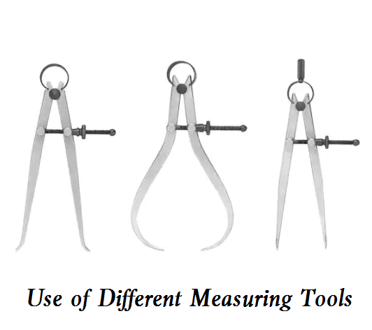
Internal and external calipers are the simplest measuring tools for comparison. The outer caliper is used to measure the outer diameter and plane, and the inner caliper is used to measure the inner diameter and groove. They can not directly read the measurement results themselves, but read the measured length dimension on the steel ruler, or take down the required dimension on the steel ruler first, and then check whether the diameter of the part conforms.
1. Adjustment of the caliper
First of all, check the shape of the jaw. The shape of the jaw has a great impact on measurement accuracy. Pay attention to the shape of the jaw frequently. When adjusting the opening of the caliper, gently tap the two sides of the caliper foot. First adjust the caliper to the opening close to the size of the workpiece with two hands, then tap the outside of the caliper to reduce the opening of the caliper, and tap the inside of the caliper to increase the opening of the caliper. But do not directly hit the jaw. This will cause measurement error because the jaw of the caliper damages the measuring surface. Never hit the caliper on the guide rail of the machine tool.
2. Use of external calipers
When the external caliper takes down the dimension on the steel ruler, the measuring surface of one clamp foot rests on the end face of the steel ruler, and the measuring surface of the other clamp foot is aligned with the middle of the required dimension line, and the connecting line of the two measuring surfaces should be parallel to the steel ruler, and the human’s vision should be perpendicular to the steel ruler. When measuring the outer diameter with the external caliper that has taken the size of the steel ruler, make sure that the line of the two measuring surfaces is perpendicular to the axis of the part. When the weight of the external caliper slides over the outer circle of the part, the feeling in our hands should be that the external caliper and the outer circle of the part are just in point contact. At this time, the distance between the two measuring surfaces of the external caliper is the outer diameter of the part to be measured. Therefore, measuring the outer diameter with the external caliper is to compare the tightness of the contact between the external caliper and the outer circle of the part. It is appropriate that the dead weight of the caliper can just slide down. For example, when the caliper slides over the outer circle, we have no contact feeling in our hands, which means that the outer caliper is larger than the outer diameter of the part. If the weight of the external caliper cannot slide over the outer circle of the part, it means that the external caliper is smaller than the outer diameter of the part. Do not put the caliper on the workpiece askew for measurement, as there is an error. Because the caliper is elastic, it is wrong to press the outer caliper hard over the outer circle, let alone clamp the caliper horizontally. For large-size external calipers, the measuring pressure of sliding over the outer circle of the part by its own weight is too high, so hold the calipers for measurement.
3. Use of internal calipers
When measuring the inner diameter with the internal caliper, the connecting line of the measuring surfaces of the two clamp feet should be perpendicular to the axis of the inner hole, that is, the two measuring surfaces of the clamp feet should be the two ends of the inner hole diameter. Therefore, the measuring surface of the lower clamp foot should be stopped on the hole wall as a fulcrum during measurement. The upper clamp foot is slightly inward and gradually outward from the orifice, and swings along the circumferential direction of the hole wall. When the swing distance along the circumferential direction of the hole wall is the smallest, it means that the two measuring surfaces of the inner clamp foot are already at the two ends of the inner hole diameter. Then move the caliper slowly from the outside to the inside to check the roundness tolerance of the hole. Measure the inner diameter with the inner caliper which has been taken on the steel ruler or the outer caliper.
Compare the tightness of the inner caliper in the part hole. If the internal caliper has a large free swing in the hole, it means that the caliper size is smaller than the hole diameter; If the inner caliper cannot be put in, or it is too tight to swing freely after being put into the hole, it means that the size of the inner caliper is larger than the hole diameter. If the inner caliper is put into the hole, it can swing freely for 1~2mm according to the above measurement method, and then the hole diameter is exactly equal to the size of the inner caliper. Do not hold the caliper by hand when measuring. In this way, it is difficult to compare the tightness of the inner caliper in the part hole which causes the caliper to deform, resulting in measurement error.
 Dial vs. Digital vs. Vernier Caliper, What’s the Difference Between Them? | CNCLATHING
 What is a Caliper Measuring Tool – Different Types of Calipers and Uses | CNCLATHING
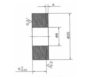
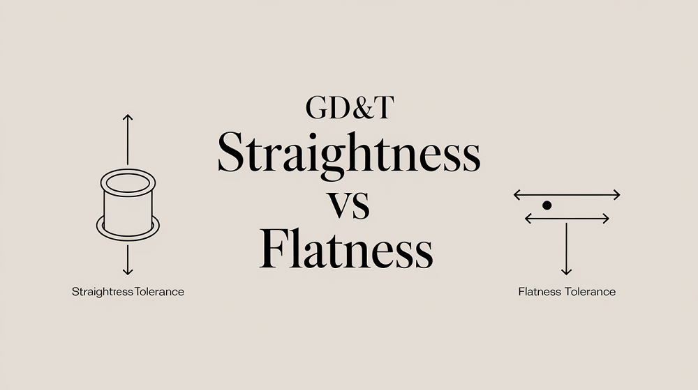 Straightness vs Flatness – Difference Between Flatness and Straightness
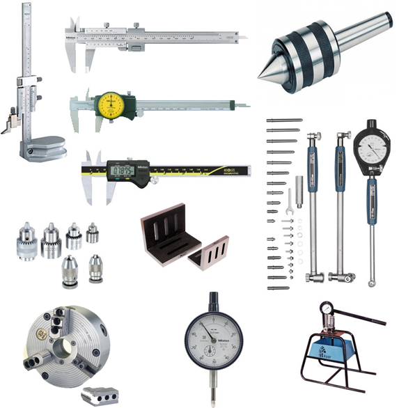 Must Have Machinists Tools | Essential Machine Shop Tools List | CNCLATHING
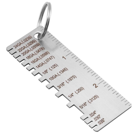 Metal Gauge Chart for Steel, Stainless, Aluminum, Brass and More | What is Sheet Metal Gauge | CNCLATHING
 Control Method Of Workpiece Thickness Of Grating Ruler And Tool Setter
