Method For Measuring Trigger Probe In 5 Axis Machining | CNCLATHING

2021.12.23

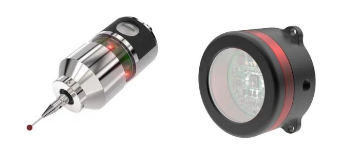
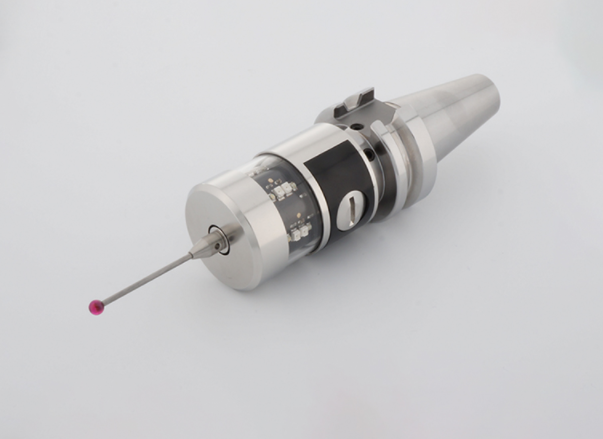
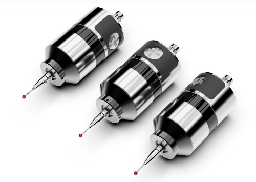
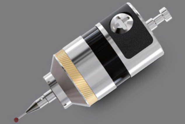
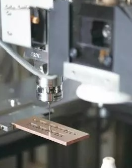
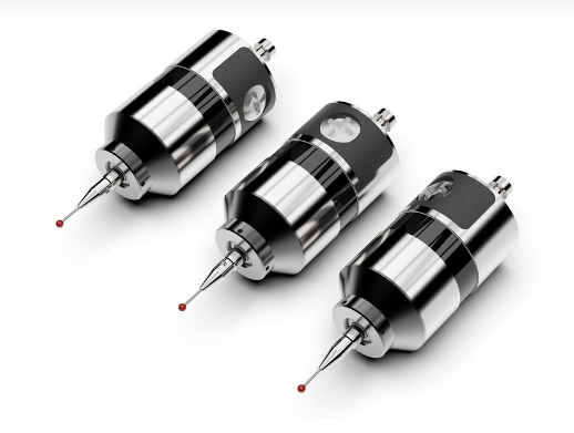
There are two methods for workpiece detection in machining center, one is off-line detection, the other is on-line detection. The traditional method of crankshaft measurement is to put the processed crankshaft on a special measuring instrument or measuring tool, which can measure the key position manually or automatically, evaluate the shape and position error of geometric elements, and complete the quality inspection. In this off-line inspection, once the size of the workpiece exceeds the tolerance, it is necessary to reinstall and align the workpiece, and then repair the deviation. This not only consumes labor time, but also is difficult to ensure the correction accuracy. Online detection can directly detect the workpiece on the machining machine tool. In case of out of tolerance, repair, processing and other measures can be taken in time to ensure the processing accuracy. On line detection technology is the development trend of quality control technology. In this guide, we detail the measurement method of trigger probe in 5 axis machining

Composition Of Measurement Process System

The on-line measurement system consists of trigger probe system, Siemens 840D CNC system and turning compound worktable.

The probe system consists of TT25, WRP and wri. The probe length is 100mm and the measuring ball diameter is 6mm. When the probe needs to be triggered continuously along different vector directions, the program controls the spindle of the machine tool to move along the vector direction to ensure that the unidirectional trigger point of the probe is aligned with the required direction. Working process: after the measurement or calibration program is started, the control system sends a command, and the probe and radio receiver enter the working state. When the probe contacts the workpiece surface and the probe rod generates a small inclination YZ in the x-axis direction or a certain contraction, the normally closed contact switch triggers the detector to open, sends a touch signal and sends a signal through the wireless module; After receiving the radio signal, the controller also sends a switch signal to the CNC system to notify the CNC system to trigger the probe. 840D CNC system has internal measurement instructions. After receiving the trigger signal, lock the current coordinates and stop the movement of the axis of the CNC machine. At this time, the current coordinate value needs to be read through the CNC command and recorded in the variable, that is, the contact coordinates. Then drive the probe backward to a safe position by command, generally 5mm. Then start the next contact measurement or return to the starting position.

Probe Calibration

According to the measurement error model of the probe system, the probe calibration evaluates the size of the standard part by collecting multiple point data of the standard part, so as to calculate the parameters in the error model. After the error model parameters are brought into the measurement, the corrected measurement value can be obtained.


The probe rotates in YZ direction and retracts in X direction. y=y+dy, z=z+dz; x=x +dx. The standard part can identify the touch deviation, directly touch two directions in one direction, and the error values in the two directions are basically the same by default.


The diameter of the ring is obtained by touching the center of the ring in the positive and negative directions of Y and Z. the difference of touch value – Theoretical diameter = trigger deviation x2. The probe can only get the value point from the X negative touch, so only the X negative trigger error needs to be calibrated. Similarly, by contacting the position of the known point on X, the difference between the read value and the known value is the calibration value.


After the calibration is completed, the workpiece can be measured. Since the measuring elements on the workpiece are mostly plane or circle and parallel or perpendicular to the coordinate axis, the positive and negative directions of XYZ axis can be selected for the touch direction of the measuring point, and the measurement compensation value is also more accurate.

Experimental Study

Before the probe works, the trigger delay deviation of the probe needs to be measured in advance to determine the position of the probe in the machine coordinate system, which is used to determine the deviation between the probe position and the actual position when the probe is triggered. The turning compound machining center is five axis three linkage, equipped with Siemens 840D control system, positioning accuracy of 10mm, equipped with MARPOSS probe, and measurement repeatability of 0.5mm.


As for the calibration procedure of the probe, marpross provides the measurement and calibration procedures of the standard machining center and ordinary lathe. However, because the coordinate system and motion mode of the turning compound machining center are inconsistent with the motion mode of the two machine tools, the measurement and calibration program cannot be used directly. Therefore, a measurement calibration subroutine based on NC instruction is developed, which can be called by users.


The steps to complete the measurement are as follows:

(1) Install the standard part with known outer diameter on the workpiece processing spindle to make the spindle axis consistent with the axis of the standard part. Or install a test rod, process the standard part with an external turning tool, and accurately clamp the diameter of the standard part with a micrometer. Contact the outer circle with the probe, and contact the measuring points according to the circle measuring principle to obtain multiple measuring points. Evaluate the diameter of the circle, then compare it with the diameter of the standard circle, and calculate the error through the model.

(2) The probe must complete tool setting before tool setting. Just like tool setting before using the tool, determine the position of the probe in the machine tool coordinate system. The length of the measuring rod and the diameter of the measuring head are written into the tool compensation to correct the position of the measuring head in the machine coordinate system.

(3) After the above work is completed, the measuring points can be picked up.

The detection program uses the G code of the machine tool to drive the probe to contact the measured point. After triggering, the machine tool stops moving, reads the coordinate value at the time of triggering, and then drives the machine tool to move in reverse to make the probe and the workpiece move back a certain distance.

FacebookLinkedInPin