
When we talk about the technological revolution in modern manufacturing, few things can compare to the contributions of Computer Numerical Control (CNC) machine tools. They are the marvels of the manufacturing world, bringing forth endless possibilities to our realm. However, few truly comprehend the inner workings and principles behind CNC machine tools. With this CNC machine block diagram guide, we will talk about the the components that make up CNC lathe tools deeply, unveiling how they collaboratively create precision, efficiency, and astonishing manufacturing wonders.
What is CNC Lathe Machine?
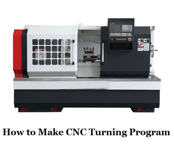
CNC machine, or Computer Numerical Control machine, or CNC lathe machine, is a type of automated manufacturing equipment that uses computerized controls and precise programming to execute a wide range of machining operations with high accuracy and consistency. These machines are commonly used in various industries, including manufacturing, aerospace, automotive, and electronics, to produce parts and components with intricate shapes and tight tolerances.
Work Principle of CNC Lathe Machine
CNC lathe machines operate based on input part machining programs. These programs contain information about the movement paths between the cutting tool and the workpiece, as well as process parameters such as feed rate and spindle speed. The machine reads this information from various input methods, including paper tapes, floppy disks, manual data input, or direct memory input from other computers or networks. Once the program is loaded, the CNC system automatically completes machining tasks based on the pre-written instructions, ensuring precision and repeatability.
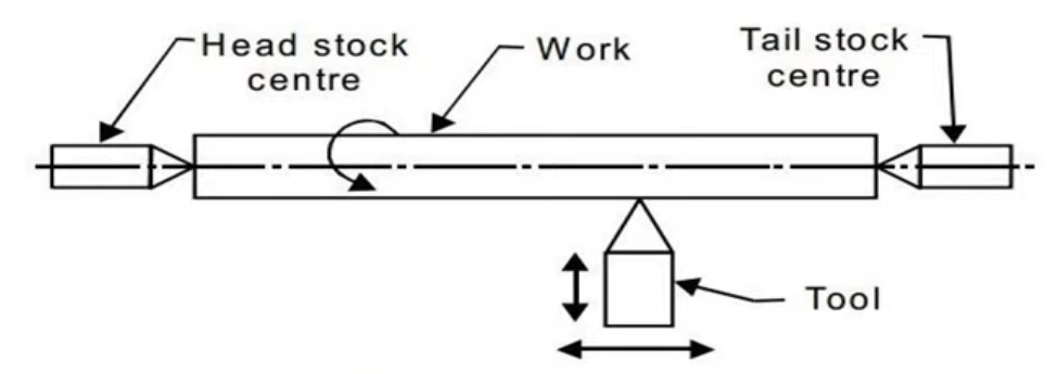
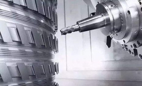
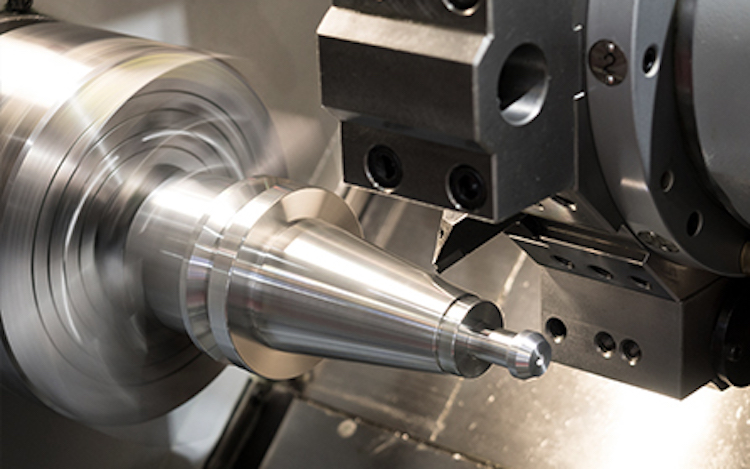
The process begins by securely clamping the workpiece, typically between two centers or within a chuck. The spindle, driven by a motor, rotates the workpiece at a controlled speed. The cutting tool, which is harder than the material being machined, is fed into the workpiece in a definite path and depth according to the programmed commands. The tool can move parallel or perpendicular to the workpiece, allowing for the creation of cylindrical, conical, or other complex surfaces, depending on the operation selected in the CNC program.
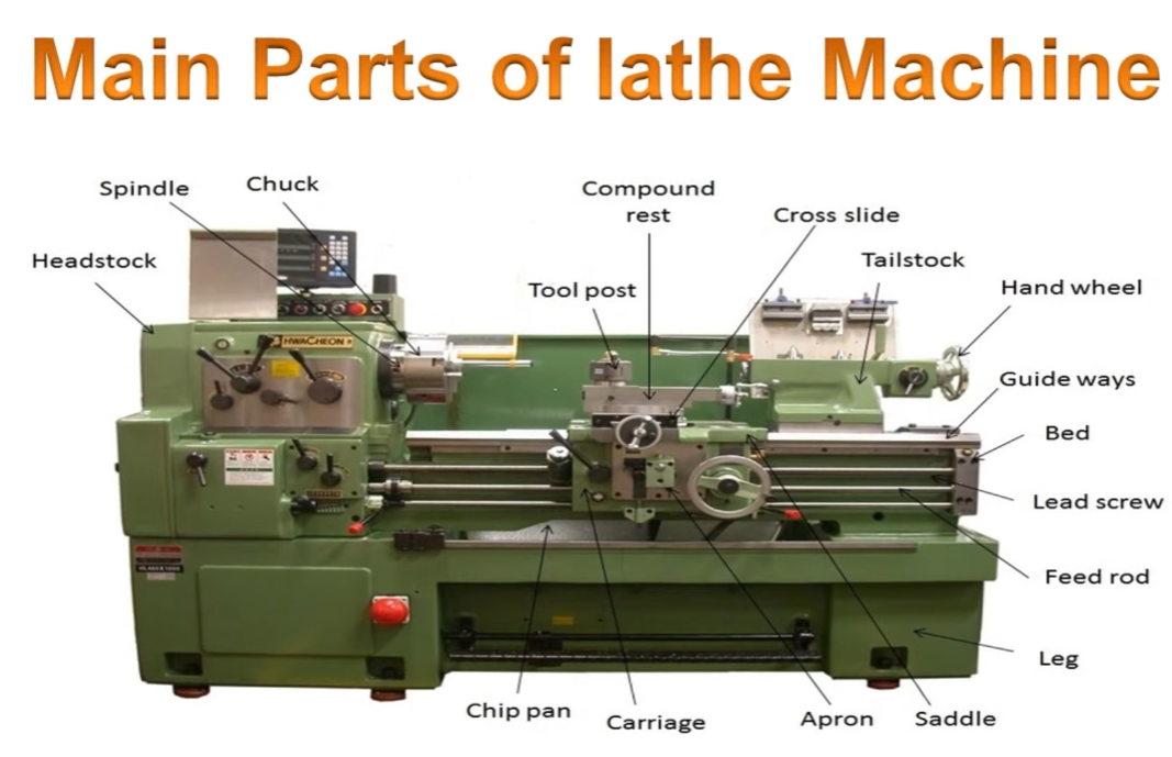
Main Components (Parts) of CNC Machine
A CNC (Computer Numerical Control) machine is a sophisticated piece of equipment used in manufacturing and machining processes to automate and control the movement of tools and workpieces with a high degree of precision.
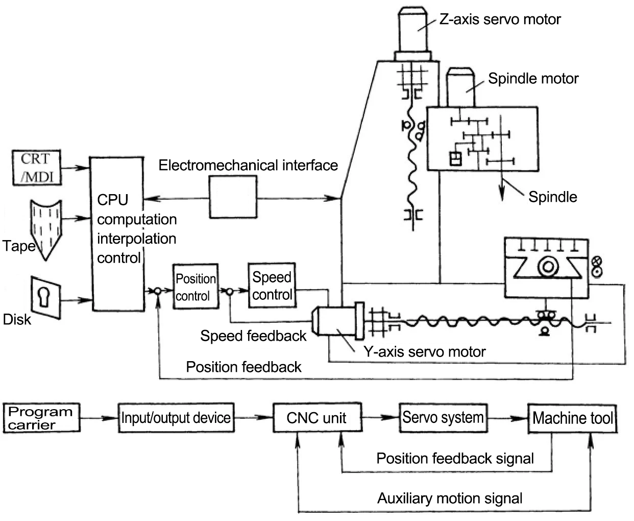
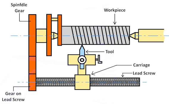
CNC Machine Block Diagram
Now let’s break down the main components of a CNC lathe machine:
CNC Lathe Machine Components
1. Computer Control Unit (CCU)
CNC machine tools operate based on input part machining programs. These programs contain information about the relative motion trajectories between the machine tool’s cutting tool and the workpiece, process parameters (such as feed rate, spindle speed, etc.), and auxiliary movements. This information is stored in a specific format and code on designated media, known as program carriers. These media can include punched tape, cassette tapes, floppy disks, and more. Using the input device of the CNC machine tool, this program information is input into the CNC (Computer Numerical Control) unit to facilitate machining operations. This allows CNC machine tools to automatically complete workpiece machining based on pre-written programs, ensuring precision and repeatability.
2. Input/Output Devices
The role of input devices is to read the CNC machining information from the program carriers into the memory of the CNC system. Depending on the type of program carrier, there are three main input methods:
(1) Control medium input: There are primarily two input methods. One method involves paper tape input, where holes are punched in a special paper tape to create different CNC codes through combinations of hole positions. These instructions are read using a tape reader. Another method is for CNC machine tools equipped with computer floppy disk drives, which can input programs stored on disks into the system.
(2) Manual input: Operators can use the machine tool’s display screen and keyboard to input machining program instructions. There are three specific scenarios:
- – Manual Data Input (MDI): In this method, CNC program instructions are entered one by one into the memory using keys on the machine tool panel. This method is suitable for shorter programs and can be used only once, as the program disappears after the machine’s operation.
- – In the program editing mode (EDIT) of the control unit, machining program instructions can be entered using keys and stored in the control unit’s memory. This allows for program editing and reuse.
- – On CNC devices with conversational programming capabilities, users can follow prompts on the screen to input relevant dimensions and other data specified on drawings, generating machining programs automatically and storing them in memory. Although this method involves manual input, it is considered automatic programming.
(3) Direct memory input: In this method, the CNC system uses communication to exchange information, directly reading machining programs that have been prepared on automatic programming machines, other computers, or networks, using specific software and parameter settings. Common communication methods on CNC machine tools include:
- – Serial interface.
- – Dedicated automatic control interfaces.
- – Network technology.
The role of output devices is to provide essential information to operators, such as program codes, cutting quantities, tool positions, fault messages, and operational instructions. Common output devices include displays and printers, while advanced CNC systems can also provide output information in a graphical format.
3. Numerical Control Unit
The Numerical Control Unit (NCU) is the most crucial component of a CNC machine tool, and the functionality of the CNC machine tool depends on the quality of the NCU. It primarily consists of three parts: input, processing, and output of information. The program carrier transfers machining information to the CNC unit through the input device, compiling it into information that the computer can recognize. The information processing section, following the control program’s specifications, gradually stores and processes this information. Subsequently, the output unit sends position and speed commands to the servo systems, which control the machine tool’s primary motion mechanism and feed transmission mechanism.
Auxiliary actions of CNC machine tools, such as tool selection and replacement, and the start/stop of coolant, can be controlled by a Programmable Logic Controller (PLC). PLCs are used for logical operations and sequence control related to input and output (I/O) and consist of both hardware and software components. PLCs applied to CNC machine tools fall into two categories: one is the integrated type, where CNC manufacturers integrate CNC and PLC for sequential control, and the other is the standalone type, developed by dedicated manufacturers, which is independent of the CNC device.
4. Servo Systems
The servo system comprises servo drive circuits and servo drive motors, including spindle servo systems and feed servo systems. The primary function of the spindle servo system is to facilitate the cutting motion during workpiece machining, with speed as the controlled parameter. The feed servo system, on the other hand, facilitates the shaping motion during workpiece machining, controlling both speed and position. It is characterized by its ability to accurately and sensitively execute position and speed commands from the CNC unit. Each component responsible for feed motion is equipped with its own set of servo drive systems. The performance of the servo drive system directly influences the speed, position, accuracy, surface roughness, and other aspects of CNC machine tool machining. The quality of the CNC machine tool’s performance relies on the effectiveness of the servo drive system.
5. Feedback Systems
Position feedback comes in two forms: angular displacement feedback for servo motors and displacement feedback for the CNC machine tool’s execution mechanism (worktable). Sensors convert these angular or linear displacements into electrical signals, which are then transmitted to the CNC unit. The CNC unit compares these signals with the instructed positions, issues commands to correct any errors, and timely controls the machine tool’s motion.
6. Mechanical Components of the CNC Machine
In addition to general components like the main drive mechanism, feed motion components (such as the worktable and tool holder), auxiliary parts (like hydraulic, pneumatic, cooling, and lubrication systems), and support components (such as the bed and column), CNC machine tools also feature special components such as tool magazines for storing cutting tools, automatic tool changers (ATC), and automatic pallet exchange systems.
Specifically:
- – Drive Motors: Drive motors are responsible for moving the various components of the CNC machine. They receive signals from the CCU and convert them into mechanical motion. Common types of drive motors include stepper motors and servo motors.
- – Axis Mechanisms: CNC machines can have multiple axes of motion, typically referred to as X, Y, and Z axes for three-dimensional machining. Each axis is equipped with linear guides, ball screws, and other mechanisms to control the movement of the cutting tool or workpiece.
- – Tool Spindle: The tool spindle holds and rotates the cutting tool. It is responsible for performing various machining operations such as drilling, milling, or turning. Some CNC machines have multiple tool spindles for multitasking capabilities.
- – Tool Changer: In CNC machining centers, an automatic tool changer is used to change cutting tools without manual intervention. It holds a selection of tools and can swap them as needed during the machining process.
- – Worktable or Workholding Fixture: The worktable or fixture holds the workpiece in place during machining. It ensures stability and accuracy. Different types of fixtures and clamping systems are used depending on the workpiece’s shape and size.
- – Coolant System: Many CNC machines are equipped with a coolant system to dissipate heat generated during machining and to lubricate cutting tools. This helps prolong tool life and maintain machining accuracy.
- – Chip Conveyor: In machining operations, chips (metal shavings) are generated and need to be removed from the work area. A chip conveyor or chip removal system helps keep the workspace clean.
- – Enclosures and Safety Features: CNC machines are often enclosed for safety reasons. These enclosures may have interlocks and safety features to protect operators from moving parts and cutting tools.
- – Special Components: Tool magazines, ATC, and automatic pallet exchange systems.
CNC Machining Operations (Parts & Diagram)
CNC lathes are capable of performing a wide variety of operations, including:
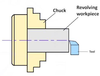
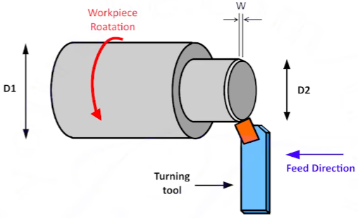
CNC Turning:
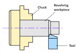
Reducing the diameter of a workpiece to create cylindrical or conical surfaces. This is achieved by moving a single-point cutting tool along the surface while the workpiece rotates.
CNC Facing:
Shortening the length of the workpiece to produce a flat surface square with the axis.
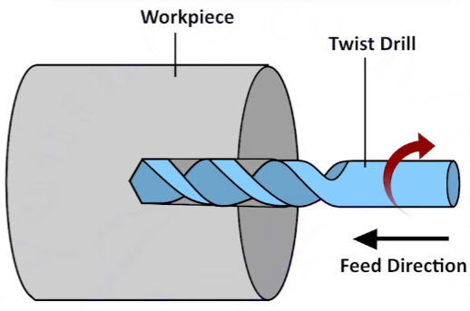
CNC Drilling:
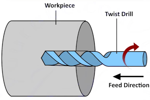
Creating cylindrical holes by advancing a rotating drill into the workpiece.
CNC Knurling:
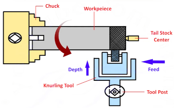
Embossing a diamond-shaped pattern onto the surface for better grip.
CNC Chamfering:
Beveling the edge of the workpiece to remove burrs and protect the ends.
CNC Milling:
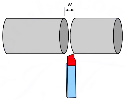
Cutting off a section of the workpiece after it has been shaped to the desired size.
CNC Boring:
Enlarging a pre-existing hole to improve its accuracy and finish.
CNC Threading:
Producing internal or external screw threads on cylindrical surfaces.
CNC Forming:
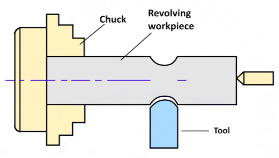
Shaping convex, concave, or irregular profiles by controlling the tool’s movement.
In comparison to conventional machine tools, CNC machine tool structures have undergone significant changes. They commonly employ features like ball screws and rolling guides, which provide lightweight, precise, and efficient transmission. These structures eliminate backlash through the use of rolling guides or plastic-coated guides. Additionally, variable speed mechanisms with main spindle motors and gearboxes have been adopted to achieve stepless speed changes while reducing the number of gear stages. CNC machine tools may also incorporate position feedback devices on their worktables, minimizing transmission clearance. Due to the typically higher operating and machining speeds of CNC machine tools compared to conventional ones, greater demands are placed on static and dynamic stiffness, vibration frequencies, and other aspects to meet the requirements for high positioning accuracy and control performance.
Related Articles:
 Types & Classification Of CNC Machine Tools | Basics Of CNC Machining
 Haas G Codes & M Codes List for CNC Lathe and Mill – Haas & Fanuc G-Code and M-Code PDF Download| CNCLATHING
 How To Deal With Failures Of CNC Machine | CNCLATHING
 What is a CNC Milling Machine & How Does it Work | Types of CNC Milling Machines
 CNC Lathe Programming Guide & Tips – How to Make CNC Turning Program | CNCLATHING
 CNC Machine Installation Tips – How To Assemble & Install CNC Machine Tools The Right Way