- Home
- Machining techniques
- CNC Machining Services
- Cooperative supply services
- Designs
- Materials
- Finishing Services
- Shop
- Products
- Guide
- About Us
- Contact Us
2020.11.9
CNC services suppliers across the world use CNC controls with the programming language to instruct the operation of the machine tool. G-code is the most widely used computer numerical control programming language, which is the core of CNC programs, also the instructions of turning and milling machines. Based on different systems, there will be subtle differences. Here you can check out the list of Haas G Codes and Haas M Codes for CNC Lathes/Mills. Also, Haas and Fanuc G-Code & M-Code PDF files are provided for download. Due to the different styles of G-code, it’s necessary to understand how your own machine uses G-code.
G00: Rapid Position Motion
G01: Linear Interpolation Motion or Linear Motion, Chamfer and Corner Rounding – Modal
G02: CW Circulation Interpolation Motion – Modal
G03: CCW Circular Interpolation Motion – Modal
G04: Dwell (P) P=Seconds. Milliseconds
G05: Fine Spindle Control Motion (Live Tooling) – Optional
G09: Exact Stop
G10: Programmable Offset Setting
G14: Main-Spindal / Sub-Spindle Swap – Optional
G15: Main-Spindal / Sub-Spindle Swap Cancel – Optional
G17: Circular Motion XYZ Plane Selection Live Tooling (G02, G03) – Modal, Optional
G18: Circular Motion ZX Plane Selection (G02, G03)
G19: Circular Motion YZ Plane Selection Live Tooling (G02, G03) – Modal/Optional
G20: Verify Inch Coordinate Positioning
G21: Verify Metric Coordinate Positioning – Modal
G28: Rapid to machine zero return through Ref. Point
G29: Move to Location Through G29 Ref. Point
G31: Feed Until skip Function – Optional
G32: Thread cutting path – Modal
G40: Tool Nose Compensation Cancel G41/G42
G41: Tool Nose Compensation, Left – Modal
G42: Tool Nose Compensation, Right – Modal
G50: Spindle Speed Maximum RPM Limit (S) – Modal
G51: Rapid to Machine zero, Cancel offset
G52: Work offset Positioning Coordinate OR Global Work Offset Coordinate System Shift – Modal
G53: Machine Zero Positioning Coordinate
G54: Work Offset Positioning Coordinate #1
G55: Work Offset Positioning Coordinate #2 – Modal
G56: Work Offset Positioning Coordinate #3 – Modal
G57: Work Offset Positioning Coordinate #4 – Modal
G58: Work Offset Positioning Coordinate #5 – Modal
G59: Work Offset Positioning Coordinate #6 – Modal
G61: Exact Stop – Modal
G64: Exact Stop G61 Cancel
G65: Macro Sub-Routine Call – Optional
G70: Finishing Cycle
G71: O.D. / I.D. Stock Removal Cycle Example
G72: End Face Stock Removal Cycle
G73: Irregular Path Stock Removal Cycle
G74: Face Grooving OR High Speed Peck Drill Cycle
G75: Peck Grooving Cycle O.D. or I.D.
G76: Threading Cycle, Multiple Pass O.D. / I.D.
G77: Live Tooling Flatting Cycle – Optional
G80: Cancel Canned Cycle
G81: Drill Canned Cycle – Modal
G82: Spot Drill / Counterbore Canned Cycle – Modal
G83: Peck Drill Deep Hole Canned Cycle – Modal
G84: Tapping Canned Cycle – Modal
G85: Bore In-Bore Out Canned Cycle – Modal
G86: Bore In-Stop-Rapid Out Canned Cycle – Modal
G87: Bore In-Stop-Manual Retract Canned Cycle – Modal
G88: Bore In-Dwell-Manual Retract Canned Cycle – Modal
G89: Bore In-Dwell-Bore-out Canned Cycle – Modal
G90: O.D. / I.D. Turning Cycle – Modal
G92: Threading Cycle – Modal
G94: End Facing Cycle – Modal
G95: Live Tooling End Face Rigid Tap – Modal/Optional
G96: Constant Surface speed, CSS On – Modal
G97: Constant Non-Varying Spindle Speed, CSS Off (S)
G98: Feed Per Minute (F) – Modal
G99: Feed Per Revolution (F)
G100: Mirror Image Cancel G101
G101: Mirror Image
G102: Programmable Output to RS – 232
G103: Limit Block Lookahead
G105: Servo Bar Command – Optional
G110-G111: Work Offset-positioning Coordinate #7-#8 – Modal
G112: Cartesian to Polar Transformation – Optional
G113: Cartesian to Polar Transformation Cancel – Optional
G114-G129: Work Offset Positioning Coordinate #9-#24 – Modal
G154: Select Work Offset Positioning Coordinate P1-99 (P) – Modal
G159: Background Pickup / Part Return – Optional
G160: APL Axis Command On – Optional
G161: APL Axis Command Off – Optional
G184: Reverse Tapping Canned Cycle – Modal
G186: Live Tooling Reverse Rigid Tap – Optional
G187: Accuracy Control for High Speed Machining (E)
G194: Sub-Spindle / Tapping Canned Cycle – Modal
G195: Live Tooling Radial Tapping – Optional
G196: Live Tooling Radial Tapping Reverse – Optional
G200: Index on the Fly
M00: Program Stop – Modal
M01: Optional Program Stop – Modal
M02: Program End – Modal
M03: Spindle on Forward (S) – Modal
M04: Spindle on Reverse (S) – Modal
M05: Spindle Stop – Modal
M08: Coolant On – Modal
M09: Coolant Off – Modal
M10: Chuck Clamp – Modal
M11: Chuck Unclamp – Modal
M12: Auto Air Jet On (P) – Modal/Optional
M13: Auto Air Jet Off – Modal/Optional
M14: Main Spindle Clamp – Modal/Optional
M15: Main Spindle Unclamp – Modal/Optional
M17: Rotate Turret Forward (T) – Modal
M18: Rotate turret Reverse (T) – Modal
M19: Orient Spindle – Modal/Optional Example
M21: Tailstock Advance – Modal/Optional
M22: Trailstock Retract – Modal/Optional
M23: Angle Out of Thread On – Modal
M24: Angle of Thread Off – Modal
M25-M28: Optional User M Code Interface with M-Fin Signal – Modal
M30: Program End and Reset – Modal
M31: Chip Auger Forward – Modal
M33: Chip Auger Stop – Modal
M36: Parts Catcher On – Modal/Optional
M37: Parts Catcher Off – Modal/Optional
M38: Specify Spindle Variation On – Modal
M39: Specify Spindle Variation Off – Modal
M41: Spindle Low Gear Override – Modal
M42: Spindle High Gear Override – Modal
M43: Turret Unlock – Modal
M44: Turret Lock – Modal
M51-M58: Optional User M Code Set – Modal
M59: Output Relay Set (N) – Modal
M61-M68: Optional User M Code Clear – Modal
M69: Output Relay Clear (N) – Modal
M76: Program Displays Inactive – Modal
M77: Program Displays Active – Modal
M78: Alarm in Skip Signal Found – Modal
M79: Alarm if Skip signal Not Found – Modal
M85: Automatic Door Open – Modal/Optional
M86: Automatic Door Close – Modal/Optional
M88: High Pressure Coolant ON – Modal/Optional
M89: High Pressure Coolant off – Modal/Optional
M93: Axis Position Capture Start – Modal/Optional
M94: Axis Position Capture Stop – Modal/Optional
M95: Sleep Mode – Modal
M96: Jump if no Signal – Modal
M97: Local Sub-Routine Call – Modal
M98: Sub-Program Call – Modal
M99: Sub-Program / Routine Return or Loop – Modal
M109: Inactive User Input (P) – Modal/Optional
M110: Tailstock Chuck Clamp – Modal/Optional
M111: Tailstock Chuck Unclamp – Modal/Optional
M119: Sub-Spindle Orient – Modal/Optional**
M121-M128: Optional User M Code Interface with M-Fin Signal – Modal
M133: Live tool Drive Forward (P) – Modal/Optional Example
M134: Live Tool Drive Reverse (P) – Modal/Optional
M135: Live Tool Drive Stop – Modal/Optional
M143: Sub-Spindle Forward (P) – Modal/Optional
M144: Sub-Spindle Reverse (P) – Modal/Optional
M145: Sub-Spindle Stop – Modal/Optional
M154: C Axis Engage – Modal/Optional Example
M155: C Axis Disengage – Modal/Optional
M164: Rotate APL Grippers To “n” Position – Modal/Optional
M165: Open APL Gripper 1 (Raw Material) – Modal/Optional
M166: Close APL Gripper 1 (Raw Material) – Modal/Optional
M167: Open APL Gripper 2 Finished Material) – Modal/Optional
M168: Close APL Gripper 2 (Finished Material) – Modal/Optional
G00: Rapid Motion
G01: Linear Interpolation Motion
G02: CW Interpolation Motion
G03: CCW Interpolation Motion
G04: Dwell
G09: Exact Stop
G10: Programmable Offset Setting
G12: CW Circular Pock Milling (Yasnac)
G13: CCW Circular Pock Milling (Yasnac)
G17: XY Plane Selection
G18: ZX Plane Selection
G19: YZ Plane Selection
G20: Inch Programming Selection
G21: Metric Programming Selection
G28: Return to Machine Zero
G29: Move to Location Through G29 Reference
G31: Skip Function
G35: Automatic Tool Diameter Measurement
G36: Automatic Work Offset Measurement
G37: Automatic Tool Length Measurement
G40: Cutter Comp Cancel
G41: Cutter Compensation Left
G42: Cutter Compensation Right
G43: Tool Length Compensation +
G44: Tool Length Compensation –
G47: Engraving
G49: G43/G44 Cancel
G50: G51 Cancel
G51: Scaling
G52: Select Work Coordinate System G52 (Yasnac)
G52: Set Local Coordinate System (Fanuc)
G52: Set Local Coordinate System (HAAS)
G53: Non-Modal Machine Coordinate Selection
G54: Select Work Coordinate System l
G55: Select Work Coordinate System 2
G56: Select Work Coordinate System 3
G57: Select Work Coordinate System 4
G58: Select Work Coordinate System 5
G59: Select Work Coordinate System 6
G60: Unidirectional Positioning
G61: Exact Stop Modal
G64: G61 Cancel
G65: Macro Subroutine Call
G68: Rotation
G69: G68 Cancel
G70: Bolt Hole Circle (Yasnac) Example1 Example2 Example3
G71: Bolt Hole Arc (Yasnac) Example
G72: Bolt Holes Along an Angle (Yasnac) Example
G73: High Speed Peck Drill Canned Cycle
G74: Reverse Tap Canned Cycle
G76: Fine Boring Canned Cycle
G77: Back Bore Canned Cycle
G80: Canned Cycle Cancel
G81: Drill Canned Cycle Example1 Example2 Ex3 Ex4 Ex5
G82: Spot Drill Canned Cycle Ex1
G83: Peck Drill Canned Cycle Ex1 Ex2
G84: Tapping Canned Cycle Example1 Peck Tapping
G85: Boring Canned Cycle
G86: Bore/Stop Canned Cycle
G87: Bore/Manual Retract Canned Cycle
G88: Bore/Dwell Canned Cycle
G89: Bore Canned Cycle
G90: Absolute
G91: Incremental
G92: Set Work Coordinates – FANUC or HAAS
G92: Set Work Coordinates – YASNAC
G93: Inverse Time Feed Mode ON
G94: Inverse Time Feed Mode OFF/Feed Per Minute ON
G98: Initial Point Return
G99: R Plane Return
G100: Disable Mirror Image
G101: Enable Mirror Image
G102: Programmable Output To RS-232
G103: Block Look ahead Limit
G107: Cylindrical Mapping
G110: Select Coordinate System 7
G111: Select Coordinate System 8
G112: Select Coordinate System 9
G113: Select Coordinate System 10
G114: Select Coordinate System 11
G115: Select Coordinate System 12
G116: Select Coordinate System 13
G117: Select Coordinate System 14
G118: Select Coordinate System 15
G119: Select Coordinate System 16
G120: Select Coordinate System 17
G121: Select Coordinate System 18
G122: Select Coordinate System 19
G123: Select Coordinate System 20
G124: Select Coordinate System 21
G125: Select Coordinate System 22
G126: Select Coordinate System 23
G127: Select Coordinate System 24
G128: Select Coordinate System 25
G129: Select Coordinate System 26
G136: Automatic Work Offset Center Measurement
G141: 3D+ Cutter Compensation
G143: 5 Axis Tool Length Compensation+
G150: General Purpose Pocket Milling
G153: 5 Axis High Speed Peck Drill Canned Cycle
G154: P1-P99 Replaces G110-G129 on newer machines
G155: 5 Axis Reverse Tapping Canned Cycle
G161: 5 Axis Drill Canned Cycle
G162: 5 Axis Spot Drill/Counterbore Canned Cycle
G163: 5 Axis Peck Drill Canned Cycle (Setting 22)
G164: 5 Axis Tapping Canned Cycle
G165: 5 Axis Bore in, Bore out Canned Cycle
G166: 5 Axis Bore in, Stop, Rapid out Canned Cycle
G169: 5 Axis Bore, Dwell, Bore out Canned Cycle
G174: Special Purpose Non-Vertical Rigid Tapping CCW
G184: Special Purpose Non-Vertical Rigid Tapping CW
G187: Accuracy Control for High Speed Machining
G188: Get Program From PST (Program Schedule Table)
M00: Program Stop
M01: Optional Program Stop
M02: Program End (Setting 39)
M03: Spindle On, Clockwise (S) (Setting 144)
M04: Spindle On, Counterclockwise (S) (Setting 144)
M05: Spindle Stop
M06: Tool Change (T) (Setting 42, 87, 155)
M08: Coolant On (Setting 32)
M09: Coolant Off
M10: 4th Axis Brake On
M11: 4th Axis Brake Release
M12: 5th Axis Brake On
M13: 5th Axis Brake Release
M16: Tool Change (T) (Same as M06)
M17: APC Pallet Unclamp and Open APC Door
M18: APC Pallet Clamp and Close APC Door
M19: Orient Spindle (P, R values optional)
M21-M28: Optional User M Code Interface with M-Fin Signals
M30: Program End and Reset (Setting 2, 39, 56, 83)
M31: Chip Auger Forward (Setting 114,115)
M33: Chip Auger Stop
M34: Coolant Spigot Position Down, Increment (+1)
M35: Coolant Spigot Position Up, Decrement (-1)
M36: Pallet Part Ready (P)
M39: Rotate Tool Turret (T#) (Setting 86)
M41: Spindle Low Gear Override
M42: Spindle High Gear Override
M50: Execute Pallet Change (P) (Setting 121 thru,129)
M51-M58: Optional User M Code Set
M59: Output Relay Set (N)
M61-M68: Optional User M Code Clear
M69: Output Relay Clear (N)
M75: Set G35 or G136 Reference Point
M76: Control Display Inactive
M77: Control Display Active
M78: Alarm if Skip Signal Found
M79: Alarm if Skip Signal Not Found
M80: Automatic Door Open (Setting 131)
M81: Automatic Door Close (Setting 131)
M82: Tool Unclamp
M83: Auto Air Jet On
M84: Auto Air Jet Off
M86: Tool Clamp
M88: Coolant Through the Spindle On
M89: Coolant Through the Spindle Off
M93: Axis POS Capture Start (P, Q)
M94: Axis POS Capture Stop
M95: Sleep Mode
M96: Jump if No Input (P, Q)
M97: Local Sub-Program Call (P, L)
M98: Sub Program Call (P, L)
M99: M97 Local Sub-Program or M98 Sub-Program Return or Loop Program (Setting 118)
M101: MOM (Minimum Oil Machining) CANNED CYCLE MODE (I)
M102: MOM (Minimum Oil Machining) MODE (I, J)
M103: MOM (Minimum Oil Machining) MODE CANEL
M109: Interactive User Input (P)
 What is Haas Control & Fanuc Control – Difference Between Haas and Fanuc | CNCLATHING
 G-Code Vs M-Code: What is the Difference Between G Code and M Code in CNC Programming
 Introduction to G-Code and M-Code in CNC Programming | G-Codes & M-Codes for CNC Turning & Milling | CNCLATHING
 Hole Machining Operations & G-Code | How to Machine/Cut a Hole on Milling Machines | CNCLATHING
 CNC Machine G-Code Tutorial – List Of G-Codes For CNC Programming | CNCLATHING
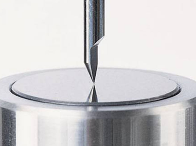 Treatment Of Common Tool Setting Problems In CNC Machining – Principle Analysis, Main Methods & Measures
