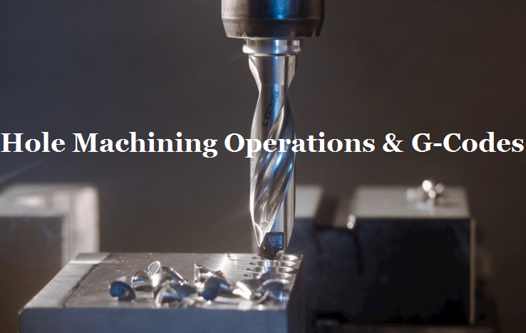
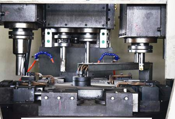
Hole is a cylindrical feature that is cut from the workpiece by feeding a rotating tool against the part. Holes can be processed in varying diameters, tolerances and depths, or machined with threads. One of hole machining operation can be done on milling machines is drilling, the most common hole making process that uses a drill bit enters the piece axially and cuts a blind hole or through-hole with a diameter equal to that of the tool. Another operation is boring, generally cuts along the internal surface of an existing hole to enlarge the diameter or get more precise measurements. Check out the list of hole drilling g-code and hole boring g-code. When processing many identical holes, we should analyze the distribution of holes, use the repeated fixed cycle reasonably, and simplify the programming as much as possible.
1) G73 – High-speed drilling cycle (small retract)
Instruction format: G73 X_ Y_ Z_ R_ Q_ F_
G73 instruction is used in hole drilling on a milling machine, retracts only as far as a clearance increment. The discontinuous feed in the z-axis direction is beneficial to chip interruption and chip removal during deep hole drilling. The instruction Q is the machining depth of each feed (increment value and positive value), and the tool withdrawal distance D is set by the CNC system.
2) G83 – Peck drilling cycle (full retract)
Instruction format: G83 X_ Y_ Z_ R_ Q_ F_
Slightly different from G73 instruction, the tool returns to R-level after each peck, it’s good for clearing flutes of chips. The value of D is set by the CNC system. This drilling method is suitable for machining deep holes. G83 also allows for dwells at the bottom of the hole. This increases the accuracy of the hole depth.
3) G76 – Fine boring cycle
Instruction format: G76 X_ Y_ Z_ R_ Q_ F_
Includes OSS and shift (oriented spindle stop and shift tool off centerline for retraction). Q is the amount of tool movement (specified as a positive value, if a negative value is used, the negative sign is ignored). After the spindle orientation at the bottom of the hole stops, the cutter head moves according to the offset specified in the address Q, and then raises the tool. The offset of the cutter head is set in the G76 command. This boring method can finish the hole machining with high precision and high efficiency without damaging the surface of the workpiece.
4) G81 Simple drilling cycle and G82 Drilling cycle with dwell (counterboring)
The instruction format of G81: G81 X_ Y_ Z_ R_ F_;
The instruction format of G82: G82 X_ Y_ Z_ R_ F_;
The only difference between G82 and G81 is that G82 has added pause at the bottom of the hole, so it is suitable for countersinking or boring step hole, which improves the machining quality of the hole step surface, while G81 instruction is only used for general drilling.
5) G85 Boring canned cycle, no dwell, feed out and G89 Boring canned cycle, dwell, feed out
The instruction format of G85: G85 X_ Y_ Z_ R_ F_;
The instruction format of G89: G89 X_ Y_ Z_ R_ P_ F_;
In these two kinds of hole processing methods, the tool is machined to the bottom of the hole in the way of cutting feed, and then returns to the R-point plane in the way of cutting feed. Therefore, it is suitable for fine boring and other situations. The G89 command adds a pause at the bottom of the hole to improve the machining quality of the step hole surface.
6) G86 – Boring canned cycle, spindle stop, rapid out
Instruction format: G86 X_ Y_ Z_ R_ F_
After machining to the bottom of the hole, the spindle stops. After returning to the initial plane or r-point plane, the spindle is restarted. In this way, if the distance between holes in continuous machining is small, the tool may have been positioned to the position of the next hole processing, but the spindle has not reached the specified speed. Therefore, the pause G04 command can be added between the hole actions to make the spindle get the specified speed.
7) G87 – Back boring canned cycle
Instruction format: G87 x_ Y_ Z_ R_ Q_ F_;
After x-axis and y-axis positioning, the spindle stops, and the tool moves in the opposite direction to the tooltip according to the Q-set offset, and quickly locates to the bottom of the hole. At this position, the tool returns according to the original offset, and then the spindle rotates forward and processes along the z-axis to z-point. At this position, after the spindle stops again, the tool moves reversely according to the original offset, and then the spindle moves up rapidly to reach the initial level Face, and return according to the original offset, the spindle rotates forward, and continues to execute the next program segment. In this way, the tool can only return to the initial plane but not to the r-point plane.
8) G88 – Boring canned cycle, spindle stop, manual out
Instruction format: G88 x_ Y_ Z_ R_ P_ F_;
When the tool reaches the bottom of the hole, the spindle stops and the system enters the feed holding state. In this case, manual operation can be carried out. However, for safety, the tool should be withdrawn from the hole first, and then machining can be started. Press the cycle start button to quickly return the tool to the r-point plane or the initial point plane, and then the spindle rotates forward.
 Haas G Codes & M Codes List for CNC Lathe and Mill – Haas & Fanuc G-Code and M-Code PDF Download| CNCLATHING
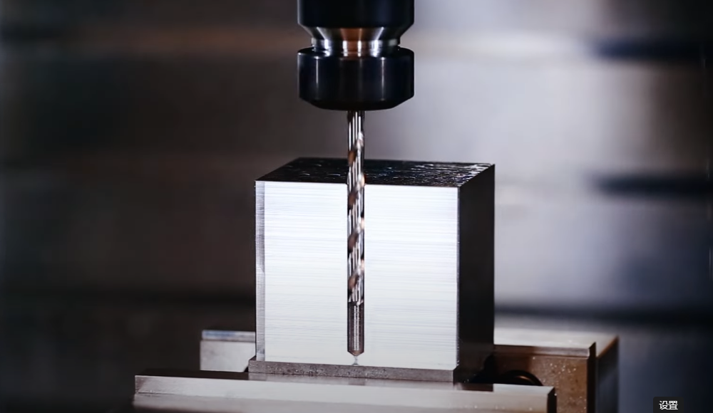 What is Peck Drilling – Peck Drilling Meaning, Cycle, G Codes, Depth, Speed, Uses & Examples
 CNC Machine G-Code Tutorial – List Of G-Codes For CNC Programming | CNCLATHING
 Guide to Boring Machining Process: Challenges, Tips and Methods of Boring Operation | CNCLATHING
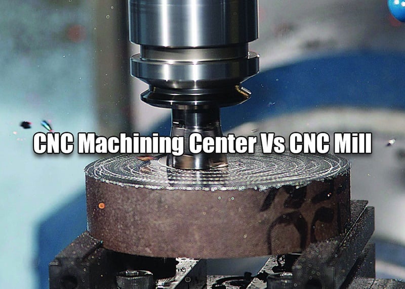 CNC Machining Center Vs CNC Mill – Difference Between Machining Center And Milling Machine In Programming
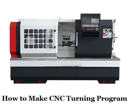 CNC Lathe Programming Guide & Tips – How to Make CNC Turning Program | CNCLATHING
