
Circularity and cylindricity tolerances are essential parameters in mechanical machining, used to describe the precision of roundness and cylindricity of parts, respectively. We will discuss the definitions, differences, calculations, and importance of these two tolerances.
In the field of mechanical machining and manufacturing, circularity and cylindricity tolerances are critical quality indicators that directly impact the accuracy and reliability of mechanical components. To ensure part quality and performance, the machining industry must place significant emphasis on controlling circularity and cylindricity tolerances, continuously improving technical and production capabilities to meet customer demands and requirements. Circularity and cylindricity are two common terms used in mechanical manufacturing, and they describe the deviations of points on a circular or cylindrical surface from the theoretical center or axis. In mechanical manufacturing, specific requirements for circularity and cylindricity tolerances must be met to ensure that parts can function properly, preventing issues such as jamming and wear. Below, we will provide a detailed explanation and comparison of circularity and cylindricity tolerances.
What is Circularity Geometric Tolerance?
Circularity is a term used to describe the extent of deviation from a perfect circle. In general, deviations are represented as the difference between the distances of various points on the diameter to the theoretical center and the minimum and maximum values. Circularity tolerance refers to the deflection caused by errors in the circular diameter during one full rotation. In practical applications, circularity tolerance is often expressed as: Circularity Tolerance = MAX – (Maximum Diameter – Minimum Diameter). A smaller value for circularity tolerance indicates a closer match between the actual circle and the ideal circle.
In mechanical manufacturing, there are strict requirements for circularity tolerance. If circularity tolerance is not met, the part may experience eccentric forces, vibrations, and other issues during operation, leading to potential part damage. Therefore, during the design and manufacturing process, efforts are made to maximize circularity tolerance to meet usage requirements.
How to Measure & Calculate Circularity?
Measuring and calculating circularity is used to determine how closely a circular object or feature approaches a perfect circle. Circularity is a common geometric tolerance used in engineering and manufacturing to ensure the roundness of a part. To measure and calculate circularity, follow these steps:
1. Measuring Equipment:
– CMM (Coordinate Measuring Machine): This is a precise measuring device that can measure the 2D coordinates of points on the circular feature.
– Roundness Tester: Specialized equipment designed specifically for measuring circularity.
– Optical Comparator: A tool that uses optical magnification to compare the shape of the feature with a perfect circle template.
– Micrometers or calipers: These can be used for basic circularity measurements, although they may not provide the same level of accuracy as the above methods.
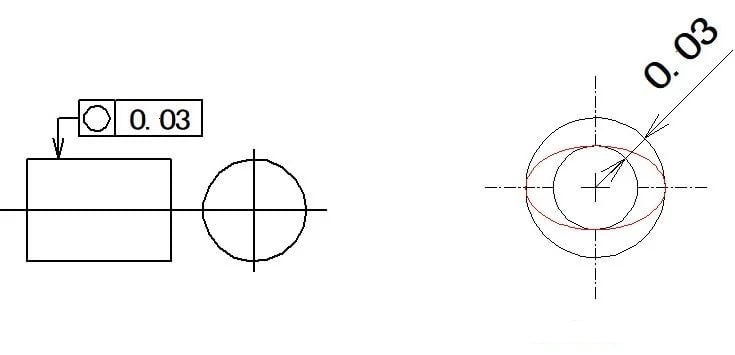
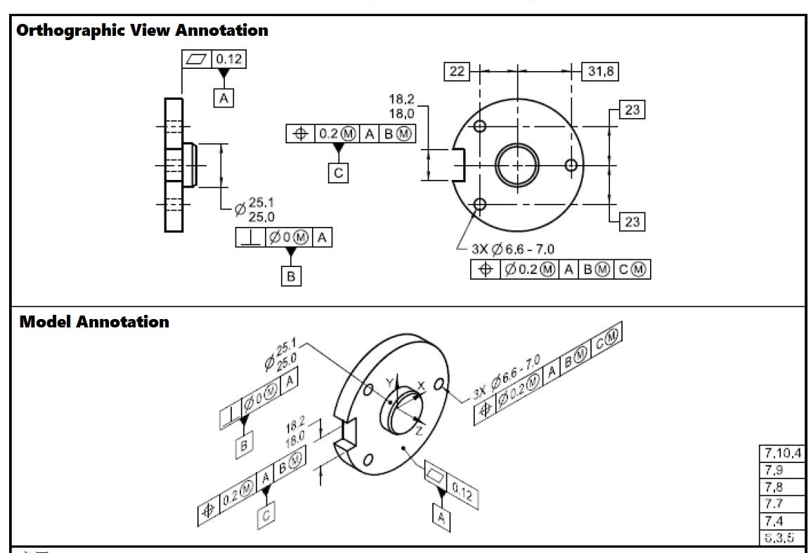
2. GD&T Tolerance Callout:
The circularity tolerance is specified on the engineering drawing using GD&T. It is represented by the circularity symbol, which looks like a circle with a diameter symbol inside. The tolerance value is expressed in micrometers (µm) or inches (in).
3. Measuring Process:
– Set up the circular part securely and accurately in the measuring equipment.
– The CMM, roundness tester, or optical comparator will then measure the 2D coordinates of points along the circular feature.
4. Calculation:
– The measured data is used to create a best-fit circle that represents the actual shape of the part.
– The deviation of each measured point from the best-fit circle is calculated.
– The maximum deviation is compared to the specified circularity tolerance to determine if the part meets the required standard.
5. Circularity Calculation Formula:
Circularity can be calculated using the formula:
Circularity = Maximum Deviation / Measured Diameter
Where:
– Maximum Deviation is the maximum distance between any measured point on the feature and the best-fit circle.
– Measured Diameter is the diameter measured on the circular feature.
It’s essential to note that the calculation of circularity can be complex, and specialized software is often used to handle the mathematical computations required to determine circularity accurately. Many measuring devices have built-in software that can automatically calculate circularity.
For critical applications or when high accuracy is needed, consult with metrology experts and use specialized equipment to ensure precise circularity measurements.
What is Cylindricity Geometric Tolerance?
Cylindricity tolerance refers to the difference between the distances of all points on a cylindrical surface to the central axis, compared to the minimum and maximum values. Its calculation method is similar to circularity tolerance. In practical applications, cylindricity tolerance is used to describe the manufacturing precision of components like the inner and outer rings of a straight roller bearing.
A smaller value for cylindricity tolerance indicates a higher degree of matching between the actual cylinder and the ideal cylinder. Similarly, if cylindricity tolerance is not met, it can lead to narrower contact areas, potentially affecting the part’s lifespan.
How to Measure & Calculate Cylindricity?
To measure and calculate cylindricity, you’ll need the appropriate measuring equipment and a basic understanding of geometric dimensioning and tolerancing (GD&T) principles. Here’s a general overview of the process:
1. Measuring Equipment:
– CMM (Coordinate Measuring Machine): This is a precise measuring device that can measure the 3D coordinates of points on the surface of the cylinder.
– Roundness Tester: Specialized equipment designed specifically for measuring the cylindricity of cylindrical features.
– Micrometers or dial indicators: These can be used for basic cylindricity measurements, though they may not be as precise as the above methods.
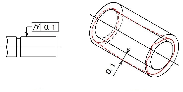
2. GD&T Tolerance Callout:
The cylindricity tolerance is specified on the engineering drawing using GD&T. It is represented by the cylindricity symbol, which looks like an elongated circle. The tolerance value is expressed in micrometers (µm) or inches (in).
3. Measuring Process:
– Set up the cylindrical part securely and accurately in the measuring equipment.
– The CMM or roundness tester will then measure the 3D coordinates of points along the cylinder’s surface.
4. Calculation:
– The measured data is processed to obtain the best-fit cylinder that represents the actual shape of the part.
– The deviation of each measured point from the best-fit cylinder is calculated.
– The maximum deviation is compared to the specified cylindricity tolerance to determine if the part meets the required standard.
It’s important to note that the calculation of cylindricity can be quite complex and is typically performed by specialized software associated with the measuring equipment. The software will handle the mathematical computations required to determine cylindricity.
Keep in mind that the specific measurement and calculation process may vary depending on the equipment and software used. If you need to measure cylindricity for critical applications, it is best to consult with metrology experts and use specialized equipment to ensure accurate results.
GD&T Circularity vs Cylindricity, Differences and Relations
The difference between circularity and cylindricity lies in the objects they describe. Circularity tolerance is used to measure the deviation of circular forms on the outer surface of a part, while cylindricity tolerance is used to measure the deviation of cylindrical surfaces. Furthermore, the calculation methods for circularity and cylindricity tolerances are slightly different, but their meanings and applications are quite similar.
1. Different geometric shapes described by circularity and cylindricity:
– Circularity tolerance is used to describe all circular forms on the outer surface of a part.
– Cylindricity tolerance is used to describe the form error on the diameter of a part.
2. Different characteristics of circularity and cylindricity:
– Circularity refers to how closely the cross-section of a workpiece matches the theoretical circle. When the difference between the maximum and minimum radii is zero, the circularity is zero. The measuring instrument for circularity is a roundness tester, and it is used to measure the circularity of annular workpieces.
– Cylindricity refers to the difference between the maximum and minimum dimensions of any vertical section. The cylindricity error includes errors in both axial and transverse sections.
3. Different calculation units for circularity and cylindricity tolerances:
– The calculation unit for circularity tolerance is length.
– The calculation unit for cylindricity tolerance is angle.
4. Different measurement methods for circularity and cylindricity:
– Circularity is mainly measured using methods such as the rotation axis method, three-point method, two-point method, projection method, coordinate method, and the direct use of data collectors connected to a dial indicator. The more acute the particle edges and corners, the worse the circularity; conversely, with smooth edges and corners, the circularity is better.
– Cylindricity is measured using methods like the two-point method, three-point method, three-coordinate measurement method, and the data collector connected to a dial indicator method. The tolerance zone for cylindricity is the area between two coaxial cylindrical surfaces, and the radial distance between these two coaxial cylindrical surfaces is the tolerance value.
5. Different representations of circularity and cylindricity tolerances:
– Circularity tolerance is represented using a shape tolerance zone.
– Cylindricity tolerance is usually represented using a restricted shape tolerance zone.
6. Different methods for determining circularity and cylindricity errors:
– Circularity is a parameter that limits the variation of an actual circle from an ideal circle, and its tolerance zone is the area between two concentric circles with a tolerance value “t” as the radius difference. Circularity tolerance belongs to form tolerance, and if the circularity error value does not exceed the corresponding tolerance value, it is considered acceptable.
– Cylindricity error refers to the variation of the actual cylindrical surface element from the ideal cylindrical surface. According to the principle of shape error evaluation, when comparing the actual cylindrical surface element with the ideal cylindrical surface, the minimum enveloping area should be determined based on the actual cylindrical surface. When two coaxial cylindrical surfaces that match the cylindricity tolerance zone closely envelop the actual cylindrical surface element and the radius difference is at its minimum, it is considered the minimum enveloping area.
7. Different application ranges of circularity and cylindricity:
– Circularity is applicable only to planar surfaces.
– Cylindricity is applicable to the entire three-dimensional part.
8. Different applications of circularity and cylindricity in the manufacturing industry:
– Circularity Application: Circularity is crucial for precision bearings, ball screws, and other parts that require high roundness. By controlling circularity, these parts can operate with lower friction and vibration, thus improving performance and longevity.
– Cylindricity Application: Cylindricity is applicable to cylindrical parts such as automotive engine cylinders and mechanical shafts. By controlling cylindricity, these parts can have precise fit during assembly, thus enhancing product reliability and durability.
Importance of Controlling Circularity and Cylindricity Tolerances
Circularity and cylindricity tolerances are critical for the quality and reliability of mechanical machining. Accurate control of circularity and cylindricity tolerances ensures the motion precision of machine components, reduces friction and wear between parts, and prolongs the machine’s lifespan. As circularity and cylindricity tolerances are parameters that directly affect the quality and reliability of mechanical machining, the machining and manufacturing industries place great emphasis on controlling and managing these tolerances. Poor control of these tolerances during mechanical machining may result in inaccurate fit and motion between mechanical parts, causing equipment to lose functionality or leading to severe mechanical failures, thus affecting work efficiency. Once such problems occur, they can result in significant losses for manufacturing factories and users.
How to Accurately Control Circularity and Cylindricity Tolerances?
Accurately controlling circularity and cylindricity tolerances is essential for obtaining high-quality mechanical parts. To ensure part quality and performance, the machining industry must focus on controlling circularity and cylindricity tolerances, continuously improving technical and production capabilities to meet customer demands and requirements. To accurately control circularity and cylindricity tolerances, the machining industry needs to adopt appropriate machining methods and tools and develop reasonable processing techniques and operating procedures. Below are some common methods and measures to consider.
1. Selecting appropriate machining techniques and technologies:
To control circularity and cylindricity tolerances, advanced machining techniques and technologies should be used, such as CNC machining, single-point turning, and grinding. These technologies not only greatly improve machining efficiency and quality but also reduce errors and deviations during the machining process.
2. Using high-precision measuring tools:
To accurately measure circularity and cylindricity tolerances, high-precision measuring tools should be used, such as coordinate measuring machines, laser interferometers, and optical platforms. These tools not only enhance measurement accuracy but also enable rapid detection of part errors and deviations, facilitating timely corrections and adjustments.
3. Strictly controlling machining parameters:
To control circularity and cylindricity tolerances, machining parameters such as cutting speed, finishing depth, tool material, and cutting fluid must be strictly controlled. This ensures both machining efficiency and quality stability.
4. Establishing reasonable quality standards and inspection methods:
To ensure the quality and stability of circularity and cylindricity tolerances, reasonable quality standards and inspection methods should be established, including relevant GB and ISO standards, such as ISO 1101. These standards not only ensure the quality of circularity and cylindricity tolerances but also improve standardization and competitiveness in the machining and manufacturing industry.
Related Articles:
 GD&T Tolerance Definitions: 14 Different Tolerances Specific to GD&T Use
 GD&T Profile Tolerance: Basic Knowledge, Types, Symbol, Calculation, Uses
 GD&T MMC: Definition, Formula, Calculation, Bonus Tolerance, Uses, MMC vs LMC
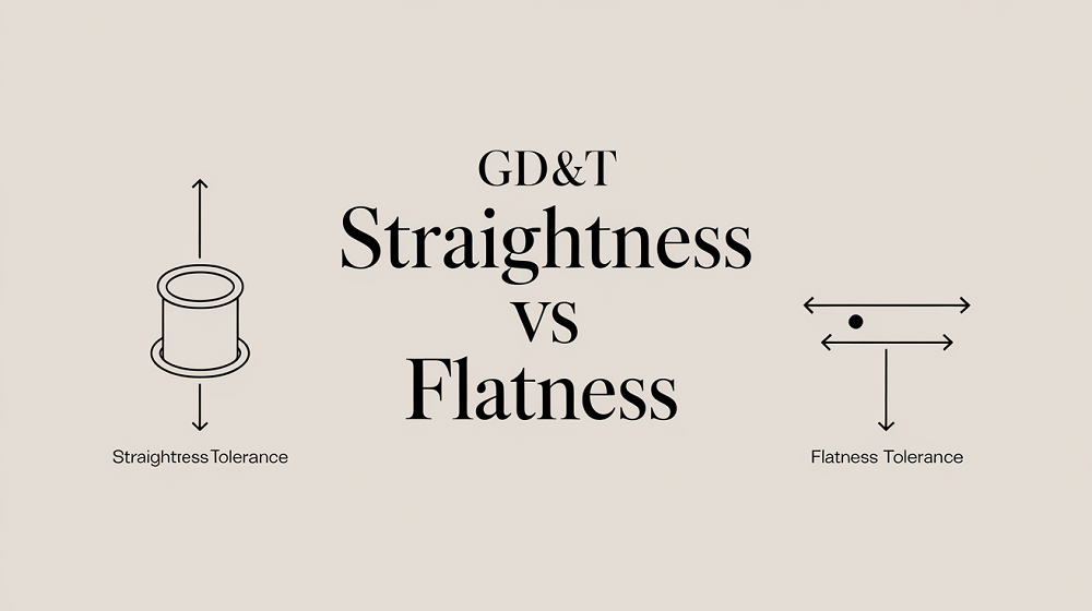 Straightness vs Flatness – Difference Between Flatness and Straightness
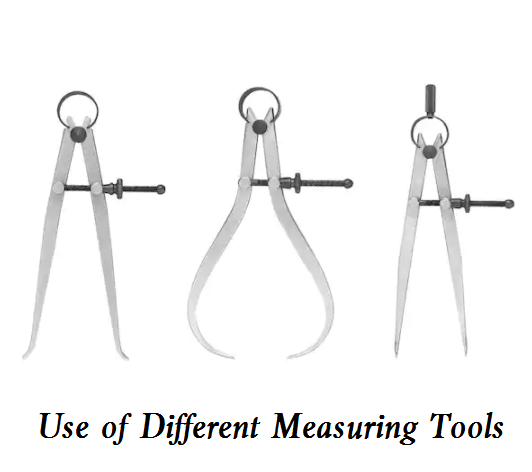 How to Use A Steel Ruler, Internal and External Caliper & Feeler Gauge
 What Is Engineering Tolerance – Types of Tolerances in Engineering Drawing