
Maximum Material Condition (MMC) is a useful modifier in GD&T that can help reduce manufacturing costs while still ensuring part functionality. By understanding what MMC means, how to calculate it, and how it can be applied to GD&T controls like position or profile, we can optimize part functionality while achieving more economical manufacturing. In this article, we will demystify MMC by covering its definition, symbol, formulas for calculation, and applications. Learning about MMC takes us one step further in mastering the world of GD&T.
GD&T Maximum Material Condition (MMC) Definition, Symbol, Formula, Calculation, Uses, MMC vs LMC
In actual applications, the size of geometric tolerances is related to the amount of material in the part features. Geometric tolerances can be applied to the maximum size, minimum size, and actual size of dimensional features, but the concept of material condition can only be applied to dimensional features (features with size). Currently, there are three common material condition states: maximum (MMC), minimum (LMC), and regardless of feature size (RFS). This article mainly explains the maximum material condition.
GD&T MMC Definition – What is the Maximum Material Condition in GD&T?
Maximum Material Condition (MMC) means the state where the maximum amount of material is contained within the specified dimensional limits (such as minimum hole diameter, maximum shaft diameter, etc.) of a feature for which size is defined.
This definition applies to both holes and shafts. To understand it from the perspective of holes and shafts:
- For holes, the maximum material condition is the minimum state of the hole.
- For shafts, the maximum material condition is the maximum state of the shaft.
GD&T MMC Symbol
The MMC symbol, represented by the letter M in a circle, signifies a condition where a part feature contains the maximum amount of material within its size tolerance.

Advantages of GD&T MMC:
1. MMC is applied relatively often in actual production manufacturing, because MMC can greatly reduce manufacturing costs.
2. MMC has compensating tolerances. When a geometric tolerance is applied to an MMC-annotated feature, additional tolerance is generated. MMC specifies the tolerance when the material is in the maximum state. When the material changes from small to large, an equal amount of size tolerance is allowed to be added to the positional size, and this increment is the bonus tolerance.
3. For parts measurement, if functional gauges (fixtures) with fixed sizes are used, and the part can fit, go/no-go gauges are used for measurement without measurement data, only pass or fail. Pass means the tolerance is met, fail means the part is not qualified. When MMC is adopted for the part, the gauge size is fixed. When the size does not reach MMC, the gauge size is the same, but bonus tolerance is allowed. Note that the additional tolerance is not obtained by deliberately sacrificing the accuracy of one feature. That error actually exists, we just convert it into usable additional tolerance with MMC.
GD&T MMC Formula & Calculation – How To Calculate Maximum Material Condition?
The calculation of MMC involves determining the virtual condition, which is the hypothetical boundary that the part must not violate to ensure proper assembly. Here’s a detailed look at how to calculate MMC for both internal and external features:
1. Calculating MMC for Internal Features
For internal features such as holes, the virtual condition is calculated as the smallest size that the feature can never exceed, ensuring that a mating part (like a pin) always fits.
GD&T MMC Formulas for Internal Features (e.g. Holes):
- Virtual Condition at MMC = Inner Boundary
- Virtual Condition = MMC Size – Geometric Tolerance
Example:
If a hole has a nominal diameter of 23.0 mm at MMC and a positional tolerance of 0.010 mm, the virtual condition would be calculated as:
- VMC = 23.0 mm – 0.010 mm = 22.990 mm
This means the smallest hole diameter, after considering the tolerance, should not be less than 22.990 mm to ensure the pin fits.
This calculation ensures that as the actual hole size increases (still within the tolerance), the assembly remains feasible, and the part can accommodate larger variations in size due to the increase in bonus tolerance.
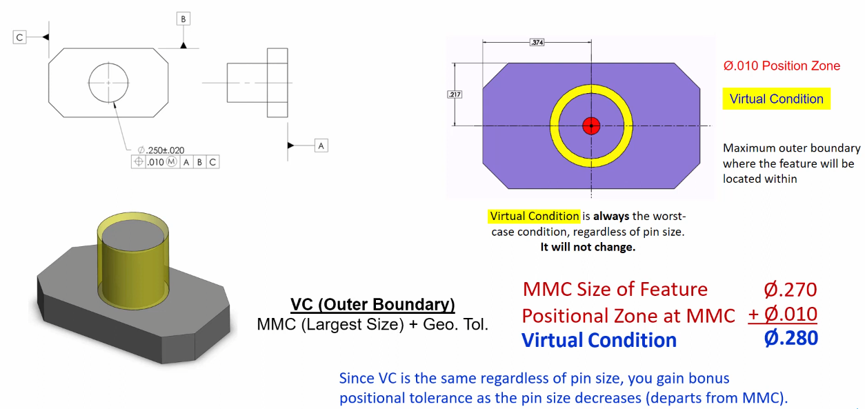
2. Calculating Virtual Maximum Material Condition for External Features
For external features like pins or shafts, the virtual condition reflects the largest boundary they can occupy, ensuring they fit into their respective mating parts.
GD&T Formula for External Features (e.g. Pins):
- Virtual Condition at MMC = Outer Boundary
- Virtual Condition = MMC Size + Geometric Tolerance
Example:
Suppose a pin has a nominal diameter of 27.0 mm at MMC with a positional tolerance of 0.010 mm, then:
- VMC = 27.0 mm + 0.010 mm = 27.010 mm
This represents the maximum boundary that the pin can occupy. The pin at its maximum material condition, plus the allowance for positional deviation, ensures it will fit into a mating part.
3. Importance of Virtual Condition in GD&T
The virtual condition is a critical concept in GD&T as it establishes a theoretical boundary for both internal and external features that parts must respect to ensure proper assembly. It serves as a safeguard against the variability in manufacturing and helps engineers design parts that are both functional and manufacturable under diverse conditions.
4. Gaining Bonus Tolerance
One of the benefits of using MMC is the possibility of gaining bonus tolerance. As the actual size of a feature deviates from its MMC (while still being within the specified limits), the part can tolerate greater positional deviations without assembly issues. This provides flexibility in manufacturing and can lead to cost savings by reducing the precision needed for certain features.
GD&T MMC Bonus Tolerance – Why Use the Maximum Material Condition?
GD&T MMC Bonus Tolerance refers to an additional tolerance that is allowed when using the Maximum Material Condition (MMC) modifier in Geometric Dimensioning and Tolerancing (GD&T).
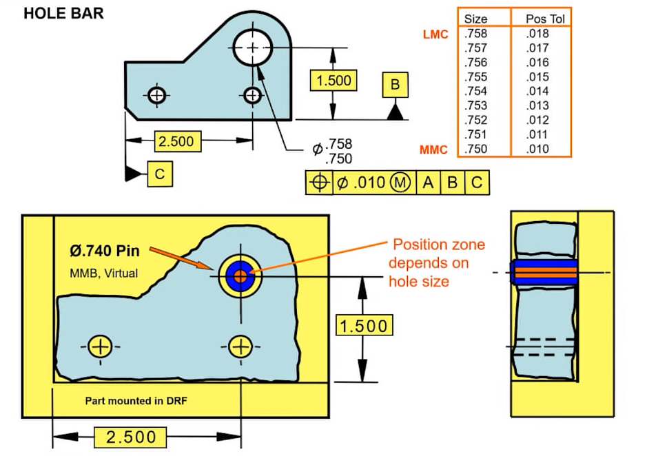
The Bonus Tolerance at MMC is:
- It provides extra tolerance when a feature is at its MMC (maximum amount of material) condition. This allows for more variation when the part is not at MMC.
- It applies to certain GD&T controls like position, profile, and runout.
- The bonus tolerance value is equal to the difference between the MMC and LMC (least material condition) sizes of the feature.
- For example, if a hole has an MMC diameter of 10 mm and LMC of 12 mm, the bonus tolerance would be 2 mm.
- So if the position tolerance at MMC is 0.1 mm, at LMC it can be 0.1 + 2 = 2.1 mm.
- It helps ensure the functionality of mating parts by providing tighter tolerance control when the part is at MMC.
- MMC bonus tolerance provides more economical manufacturing by allowing looser tolerances away from MMC.
GD&T MMC Example – How to Calculate Bonus Tolerance of Maximum Material Condition?
To better understand the application of GD&T MMC in machining and how it helps reduce costs, let’s explore an example:
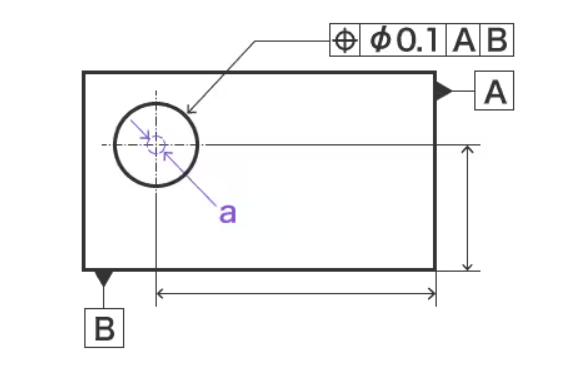
1. Scenario Without Maximum Material Condition Requirement
In Figure 1, the positional tolerance is indicated without considering the Maximum Material Condition (MMC), meaning the hole’s deviation must be within a diameter of 0.05mm, and the size tolerance of the hole and its positional tolerance are independent of each other.
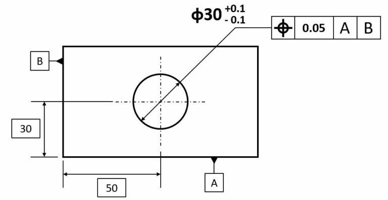
When MMC is Applied:
In Figure 2, the positional tolerance frame includes the “M” symbol, indicating that the positional tolerance now considers the MMC. This links the size tolerance of the hole to its positional tolerance, creating a floating tolerance zone. This relationship means the positional tolerance will vary with the size of the hole:
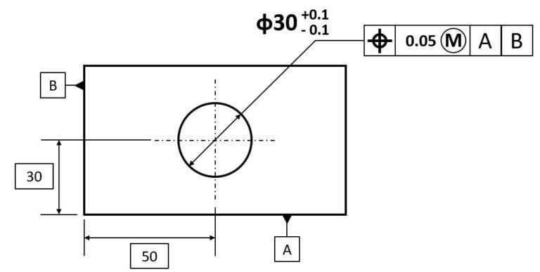
- At MMC: The hole is at its smallest diameter, preserving the most material (29.9mm), setting the positional tolerance to the original specified value of 0.05mm.
- Above MMC: At a hole diameter of 30.1mm, the entire tolerance range of 0.2mm is added, changing the positional tolerance to 0.25mm.
The relationship between the positional tolerance and the hole size can be referred to in a table that outlines how positional tolerance adjusts with the hole’s diameter.
If we consider a shaft feature:
At Maximum Material: When the shaft is at its largest diameter (30.1mm), the positional tolerance remains 0.05mm.
Below Maximum Material: At a smaller diameter (29.9mm), positional tolerance increases to 0.25mm.
Why Use MMC to Create a Floating Tolerance Zone?
The primary consideration here is assembly. For a shaft, a smaller diameter increases the likelihood of successful assembly without requiring tight positional tolerances, thus reducing machining costs to achieve the same assembly outcome.
2. Applying MMC to Datum Requirements
Now, let’s look at applying MMC to datum requirements, as seen in Figure 3:
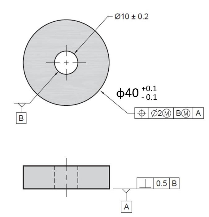
Without considering MMC, the verticality of the base must be within 0.5mm of being perpendicular to datum axis B, and the concentricity of the outer contour must be within a 2mm diameter centered on the hole axis.
Adding the “M” symbol to the tolerance frame creates a floating tolerance zone, relaxing the tolerance requirements. Similarly, adding the “M” symbol to the datum frame allows for datum shift, a concept in GD&T where the datum feature can move within specified limits.
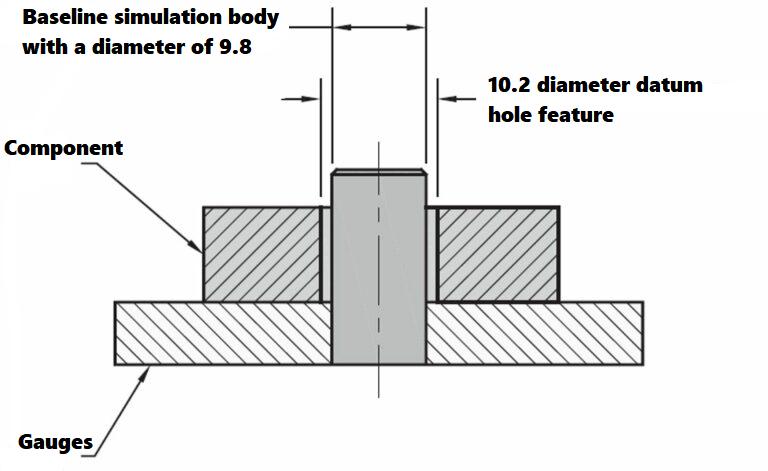
In Figure 3, adding the “M” symbol to datum B means it follows the MMC principle, setting the datum feature simulator based on the condition of maximum material retention. As illustrated in Figure 4, the datum hole feature relative to the datum feature simulator has a permissible deviation of ±0.2mm.
When both the tolerance frame and datum frame include the “M” symbol, not only does the tolerance become floating, but the measurement datum also includes a shift. For instance, in Figure 3, with a shaft diameter of 40.1mm, the positional tolerance is 2mm, which increases to 2.2mm for a diameter of 39.9mm. The datum hole feature with a diameter of 9.8mm also allows a single-side datum shift of up to 0.2mm. Therefore, the maximum permissible deviation is calculated by adding the floating tolerance band to the datum shift compensation:
- For a diameter of 40.1mm: 2 + 0.2 = 2.2mm
- For a diameter of 39.9mm: 2.2 + 0.2 = 2.4mm
This example illustrates how MMC can be strategically used in GD&T to optimize manufacturing processes and ensure efficient assembly while maintaining flexibility in tolerances.
GD&T MMC Applications – How To Use the Maximum Material Condition in GD&T?
Due to its widespread use in practical assemblies, this paper will discuss the applications of MMC (Maximum Material Condition) through a few simple examples, to facilitate a detailed understanding of the maximum material principle.
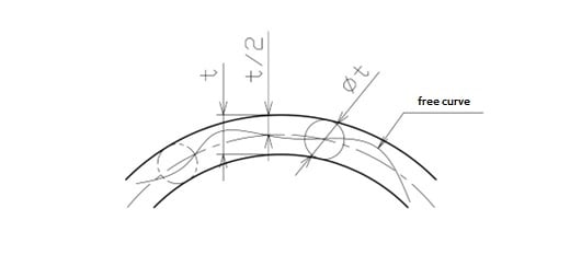
1. MMC Applied to Straightness
When MMC is applied to straightness, as illustrated below, the tolerance for maximum straightness is the specified tolerance plus the offset of the actual local size of the feature relative to its MMC size. The derived median line of the actual feature under MMC must be within the specified cylindrical tolerance zone. When each actual local size deviates from the MMC entity, the local diameter of the tolerance zone is allowed to increase, with the increment equal to that offset. However, the actual size of each circular element on the surface must be within the specified size limits.
2. MMC Applied to Position Tolerance
For position tolerances under MMC, interpretation can be based on the surfaces or axes of the dimensional features. When there are deviations in the shape or direction of the dimensional features, the tolerance requirements based on the axis method differ from those based on the surface method. The surface method should be prioritized. As shown in the example below, errors in axis method interpretation caused by shape deviations should be carefully avoided.
Surface Method: While ensuring the specified size limits of the feature, no element of the surface may invade the theoretical boundary located at the theoretical position.
Application of Axis or Central Plane Method: When a dimensional feature is at MMC, its axis or central plane must be within the tolerance range at the theoretical position. The size of this tolerance zone is equal to the positional tolerance.
3. MMC Applied to Zero Tolerance
The application of MMC to zero tolerance is also relatively common, but it often occurs in requirements for reference holes. As shown below, a zero tolerance is required for perpendicularity when the feature is at MMC, i.e., at 50 mm, the perpendicularity is zero. When the diameter of the hole feature is 50.16 mm, 0.16 mm will compensate for the perpendicularity, setting the perpendicularity tolerance at 0.16 mm.
GD&T MMC vs LMC – What are The Differences Between MMC and LMC?
In GD&T, Maximum Material Condition (MMC) and Least Material Condition (LMC) are essential concepts that help manufacturers save costs while ensuring that parts meet functional specifications. Here’s a clearer breakdown of these two conditions.
Maximum Material Condition (MMC)
MMC refers to the state of a feature where it contains the maximum amount of material. The implications of MMC vary depending on whether the feature is external or internal:
- External Features (e.g., shafts): MMC is achieved when the feature is at its largest permissible size. For instance, a shaft with an outer diameter spec of 10 mm + 0.1 mm reaches MMC at 10.1 mm.
- Internal Features (e.g., holes): MMC occurs when the feature is at its smallest permissible size. A hole with a diameter specified as 10 mm + 0.1 mm is at MMC when it measures 9.9 mm.
MMC is particularly useful in assembly as it ensures that parts will fit together under the worst-case scenario of maximum material presence. It also allows for the application of bonus tolerance, where additional tolerance can be used if the feature does not reach its MMC size.
Least Material Condition (LMC)
Contrary to MMC, LMC is the condition where the feature contains the least amount of material:
- For an external feature like a shaft, LMC is when it is at its smallest size.
- For an internal feature like a hole, LMC is when it expands to its largest possible size.
LMC is useful for applications where the strength of the material is critical, as it ensures that the part will still function despite having the minimal amount of material.
Using MMC and LMC allows manufacturers to adjust tolerances based on the actual conditions of the parts. For example, when specifying the position tolerance for a hole that is meant to be at MMC (e.g., a hole diameter of 5 mm with a tolerance of +0.1 mm), the feature control frame might include an “M” symbol to indicate MMC. This symbol implies that the stated tolerance applies only at the MMC size of 4.9 mm. However, if the actual hole size is larger, say 5 mm or 5.1 mm, additional tolerance can be utilized, increasing the positional tolerance from the nominal 0.1 mm to 0.2 mm or even 0.3 mm, respectively.
Related Articles:
 GD&T Profile Tolerance: Basic Knowledge, Types, Symbol, Calculation, Uses
 Straightness vs Flatness – Difference Between Flatness and Straightness
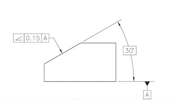 GD&T Angularity Definition, Symbol, Callout, Measurement, Tolerance & Angularity vs Profile
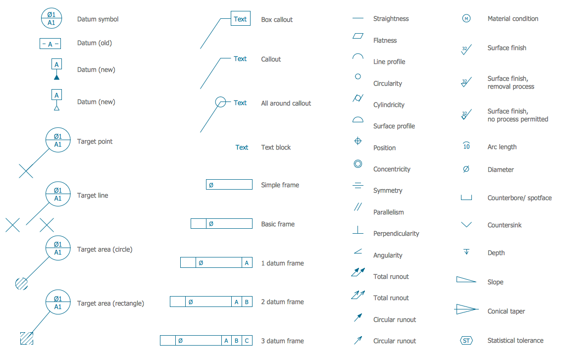 Engineering Drawing Abbreviations and Symbols – Technical & Mechanical Design Symbols | CNCLATHING
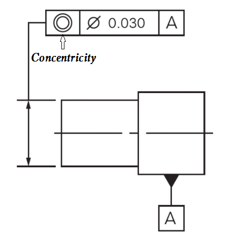 What is Concentricity in GD&T – How to Measure, Calculate Concentricity & Concentricity vs Runout
 GD&T Position and True Position Definitions, Calculations & Differences Between Them