- Home
- Machining techniques
- CNC Machining Services
- Cooperative supply services
- Designs
- Materials
- Finishing Services
- Shop
- Products
- Guide
- About Us
- Contact Us
2020.10.21
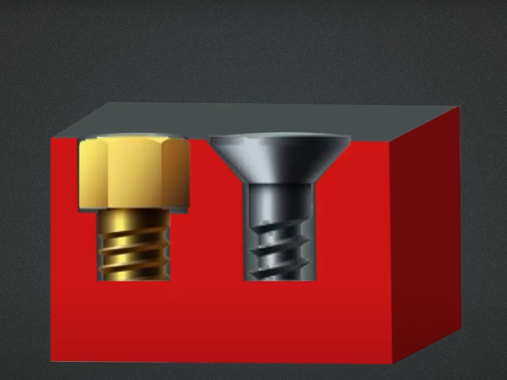 Counterbore vs Countersink in CNC Drilling: Differences in Symbol, Shape, Size, Tool, Application
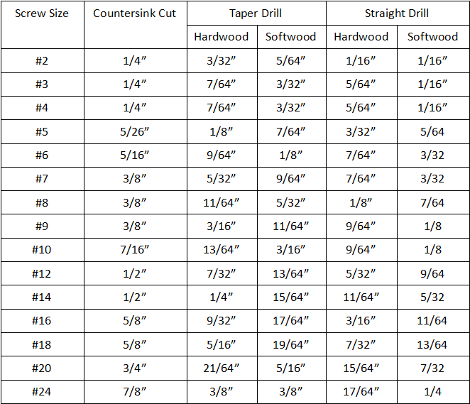 Countersink Size Chart (Hole & Drill Bit) | What Is a Countersink Drill Bit & & How to Use
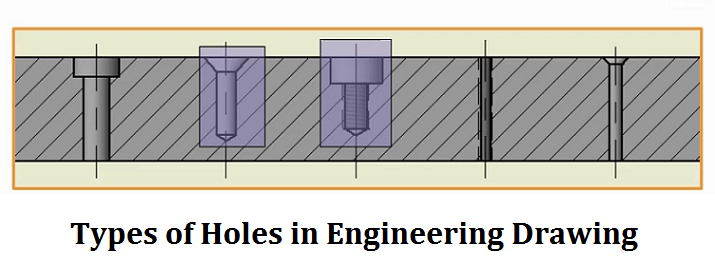 Types of Holes in Engineering Drawing & Hole Machining Operations
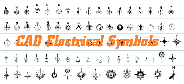 CAD Electrical Symbols Blocks | CAD Electrical Drawings Free Download | CNCLATHING
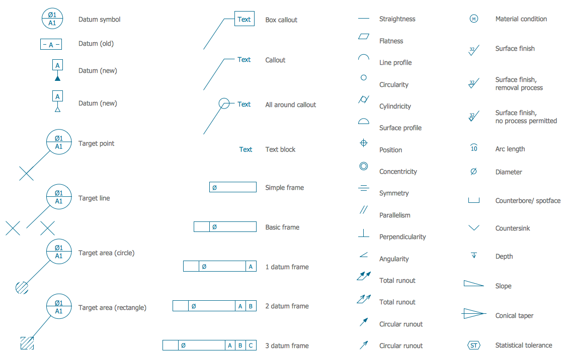
 What Is Engineering Tolerance – Types of Tolerances in Engineering Drawing
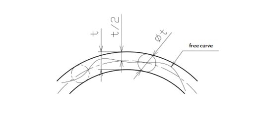 GD&T Profile Tolerance: Basic Knowledge, Types, Symbol, Calculation, Uses
