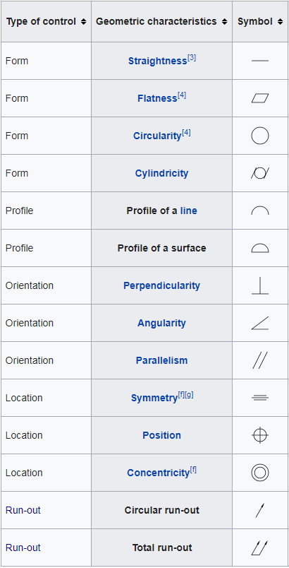
1. Form controls
Straightness: a tolerance that controls the form of a line somewhere on the surface or the feature.
Flatness: a symbol that references how flat a surface is regardless of any other datums or features.
Circularity: also called roundness, a 2-Dimensional tolerance that describes how close an object should be to a true circle.
Cylindricity: a 3-Dimensional tolerance that controls the overall form of a cylindrical feature to ensure that it is round enough and straight enough along its axis.
2. Profile controls
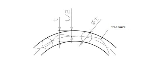
Line profile: a two-dimensional tolerance range that that limits the amount of error for line elements relative to their true profile.
Surface profile: a three-dimensional tolerance limits the amount of error a surface can have relative to its true profile, applies to all line elements collectively.
3. Orientation controls
Angularity: specifies a tolerance zone defined by two parallel planes at the specified angle other than 90 degrees from a datum plane or axis within where the surface or the axis of the feature must lie.
Perpendicularity: a three-dimensional geometric tolerance that controls how much a surface, axis, or plane can deviate from a 90-degree angle
Parallelism: the condition of a surface or center plane equidistant at all points from a datum plane, or an axis.
4. Location controls
Position: the location of one or more features of size relative to one another or to one or more datums.
Concentricity: a condition in which the axes of all cross-section elements of a feature’s surface of revolution are common to the axis of a datum feature.
Symmetry: a three-dimensional geometric tolerance that controls how much the median points between two features may deviate from a specified center plane or axis.
5. Runout controls
Circular runout: can be defined as two-dimensional geometric tolerance that controls the form, orientation, and location of multiple cross sections of a cylindrical part as it rotates.
Total runout: involves tolerance control along the entire length of, and between, two imaginary cylinders, controls cumulative variations in circularity, coaxiality, straightness, taper, angularity, and profile of a surface.
 GD&T Profile Tolerance: Basic Knowledge, Types, Symbol, Calculation, Uses
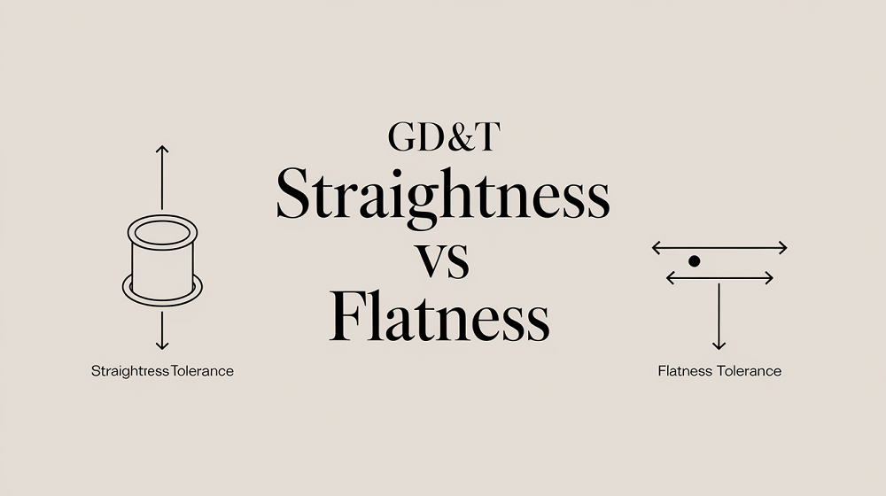 Straightness vs Flatness – Difference Between Flatness and Straightness
 CAD Electrical Symbols Blocks | CAD Electrical Drawings Free Download | CNCLATHING
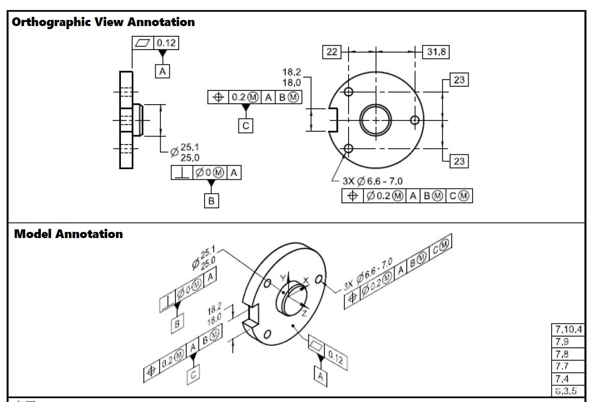 GD&T MMC: Definition, Formula, Calculation, Bonus Tolerance, Uses, MMC vs LMC
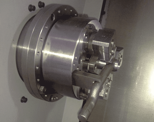 Application Of Error Compensation In Improving Machining Accuracy | CNCLATHING
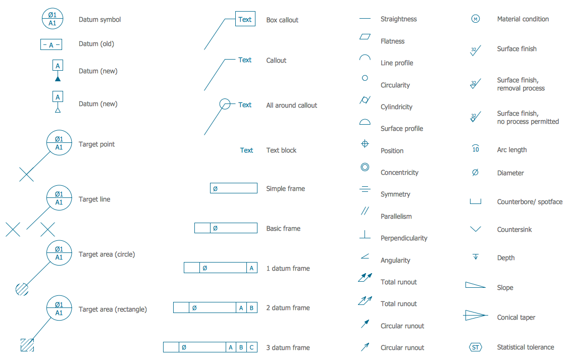 Engineering Drawing Abbreviations and Symbols – Technical & Mechanical Design Symbols | CNCLATHING
