
The creation and use of tolerance in engineering is purposed to specify the boundary of qualified products, what is the definition of engineering tolerance? And what are the common types of tolerances used in engineering drawing? In this post, we are going to better understand the engineering tolerance.

What Is Engineering Tolerance?
Deviations around the target value often exist during the manufacturing of machined parts, based on the use of the product, tolerance is created to allow for reasonable variations. Engineering tolerance is a specified acceptable range of deviation in measurements relative to the base value. Different tolerances guarantee the products meet the required specifications and function properly.
Why tolerance is important in engineering?
- Tight tolerances will ensure the accuracy of machined parts, avoid multiple productions, save time and resources.
- Tolerance limits allow for different parts with same specification to fit each other or be interchanged.
- Strict tolerances reduce the number of defective parts and improves quality.
- The system performs best when variations are minimized.
- Within the tolerances, mass production of identical parts at competitive price is possible.
What is an example of tolerance in engineering?
For instance, the hole diameter tolerance is the permitted deviation from the nominal diameter for a hole that a part must fit into. ±0.005mm is an example of a tight tolerance.
How to determine tolerance in engineering drawing?
Tolerances should be set in a way that does not significantly affect other factors or the outcome of a process. Process capability, measurement error, and statistical uncertainty should be taken into account when setting tolerances. The intended statistical sampling plan and acceptable quality level may also influence the choice of tolerances.
Types of Tolerances in Engineering Drawing
Tolerances in engineering drawing include dimension tolerance, shape tolerance, position tolerance, general tolerance, and more. Let’s dive into the common tolerances used in engineering drawing.
1) Dimension tolerance: refers to the acceptable variation in sizes like lengths, widths, thicknesses, radii, etc.
- Bilateral Tolerance: specifies a variation in both directions from the nominal dimension. For example, if a part has a nominal size of 50 mm with a tolerance of ±0.5 mm, it means the part can be between 49.5 mm and 50.5 mm.
- Unilateral Tolerance: specifies a variation in only one direction (either positive or negative) from the nominal dimension.
- Limit Tolerances: specifies the upper and lower limits for a dimension directly.
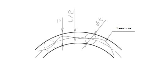
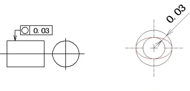
2) Geometric/shape tolerance: refers to the allowable variation in the shape of a part’s feature from its ideal geometric form. For example, if you have a flat surface that must be within a certain tolerance for the product to function correctly, you might specify a flatness tolerance.
- Straightness: deviation from an ideal straight line
- Flatness: deviation from the ideal plane.
- Circularity: deviation from the ideal circle.
- Cylindricity: deviation from ideal cylinder.
- Profile tolerance: deviation for curves/surfaces.
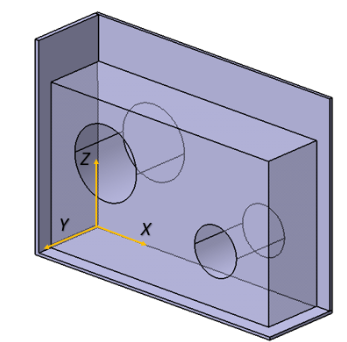
3) Position tolerance: specifies the allowable deviation for the location of a feature from its exact position.
- Directional tolerance: variation in direction
- Location tolerance: variation in position
- Runout tolerance: for tests like circular runout
4) General tolerance: provided in standards like ISO 2768 for unspecified dimensions, provide acceptable tolerance ranges for unspecified dimensions on a drawing.
- Linear tolerance: Specifies acceptable variation for linear dimensions like lengths, widths, thicknesses, etc.
- Angular tolerance: Defines permissible error in specified angles between surfaces or axes.
- External radius tolerance: Limits deviations for radii of external cylindrical features.
- Chamfer height tolerance: Governs variability in heights of chamfered/filleted edges.
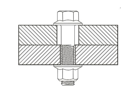
5) Fits: refers to the clearance between two mating parts.
- Clearance fit: shaft smaller than the hole.
- Interference fit: shaft larger than the hole.
- Transition fit: some overlap allowing either.
6) GD&T (Geometric Dimensioning and Tolerancing): a comprehensive system that covers various types of tolerances.
List of Engineering Tolerance Symbols
Common engineering tolerance symbols:
∅ (phi): Indicates diameter dimension
+/-: Indicates upper and lower deviation from nominal
±: Indicates total toleranced width from nominal
Ø: Alternate symbol for a diameter dimension
×: Indicates multiplication
μ: Micron (prefix symbol for micrometers)
°: Degree
‘: Minutes (unit of angle)
“: Seconds (unit of angle)
mm: Millimeters
in: Inches
mas: Minutes of arc (unit of angle)
c: Clearance tolerance
L: Limit dimension
M: Maximum material condition
N: Nominal dimension
R: Reference dimension
PCD: Pitch circle diameter
P: Projected tolerance zone
W: Basic dimension
A: Actual dimension
BTM: Basic tolerance of manufacturing
BTR: Basic tolerance of repair
PT: Parallelism tolerance
GD&T symbols:
⊥: Perpendicularity
∆: Angularity
∥: Parallelism
=: Concentricity
C: Circular runout
TIR: Total indicator reading
Related Articles:
 GD&T Tolerance Definitions: 14 Different Tolerances Specific to GD&T Use
 GD&T Profile Tolerance: Basic Knowledge, Types, Symbol, Calculation, Uses
 Clearance Hole Size Chart for Metric and Imperial Fasteners (Bolts, Screws & Studs)
 Spindle Bearing of Lathe – Adjustment of Radial Clearance and Axial Clearance
 What is the Difference Between Circularity and Cylindricity Geometric Tolerance?
 Casting Geometric Tolerances (GD&T) Charts: Straightness, Flatness, Roundness, Parallelism, Perpendicularity, Concentricity Tolerance Tables