
For most measurement workers in the CNC machine shop, the coordinate measuring machine (CMM) is not strange. CNClathing.com uses CMM machines every day to take the inspection and verification on products from CNC machining and other processes, to ensure each part is produced in the right dimensions and geometries. This is one of the methods we carried out to ensure our products are qualified and meet the customer requirements. Follow us to learn about the coordinate measuring machine (CMM) definition, diagram, working principle, types, applications, and how to use it.
What Is a Coordinate Measuring Machine – What Does a CMM Machine Do?
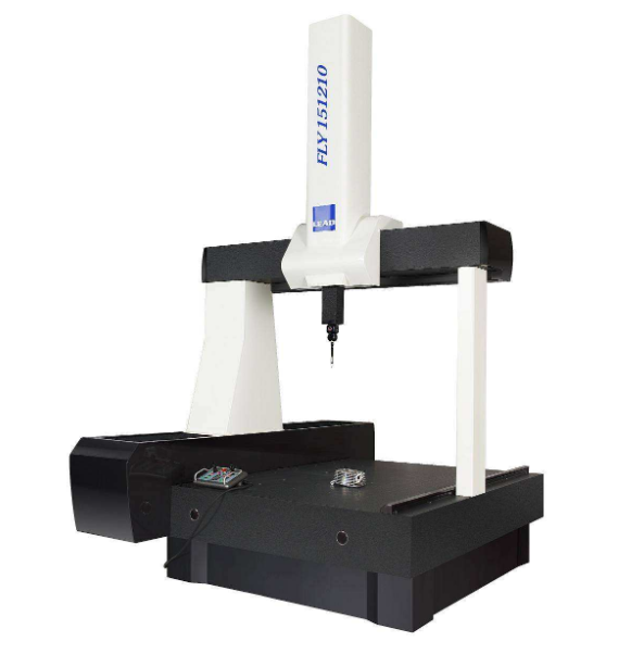
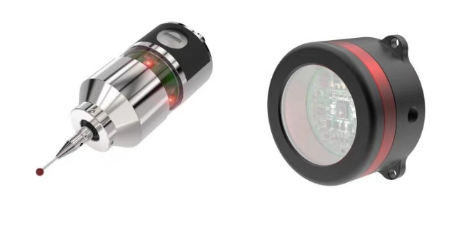
The meaning of CMM in engineering is coordinate measuring machine, which is a device that is used to measure the geometric features (lines, circles) and geometric dimensioning & tolerancing parameters (angularity) of physical objects by sensing discrete points on the surface of objects. The purpose of CMM machines is to test if the part or assembly conforms to the design or required specifications. Coordinate measuring machines can get the data through contact or non-contact methods. Contact models usually use touch probes, and the other type often utilizes laser technology and cameras.
The first CMM was created by Ferranti (a British company) and publicly shown in 1959. These early machines measured objects in three dimensions (X, Y, Z) by manually moving a probe. They improved accuracy but were slow and required skilled operators. In the 1970s, computers were added to control CMMs automatically, and more complex parts could be inspected at higher speeds. Modern CMMs use advanced software to analyze data, create 3D models, and provide real-time feedback to get the most accurate results.
CMM has been widely used in the measurement of the machined parts and accessories applied in mechanical manufacturing, automobile, electronics, aerospace, military and defense, furniture, and tool prototype; the box, frame, gear, cam, worm wheel, worm, blade, curve, curved surface, and more in molding industry; as well as hardware, plastic and other fields to measure the size, shape and position tolerance of the workpiece, so as to complete the parts inspection, shape measurement, and process control.
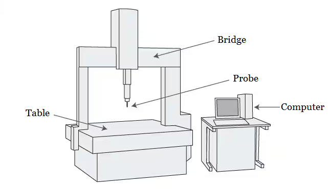
Bridge Type CMM Diagram
Advantages of CMM Machines
- High accuracy and precision in dimensional measurements.
- Provides consistent and repeatable results without human errors and variations.
- Higher efficiency and reduced time compared to manual inspections.
- Visual 2D or 3D displays or data that can be used for analysis.
Limitations of CMM Machines
- Not suitable for mass production runs that require high-speed measurement.
- Can only measure the part surfaces using probe tips to touch them; the internal features can’t be inspected.
- May cause deformation when working with soft materials, which potentially results in wrong readings.
- Large-sized CMMs require a large space in a properly controlled environment.
- The operations and data analysis need specialized training and expertise.
How Does a CMM Machine Work – Working Principle of CMM Machines
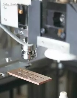
The coordinate measuring machine (CMM) operates on a system of three axes: X, Y, and Z, which allow it to move the probe accurately in three-dimensional space. This setup works similarly to how a finger might trace points on a map, but the probe touches specific points on the object, each defined within the machine’s coordinate system. The object to be measured is placed on a stable, rigid work table, which ensures accurate and consistent measurements by preventing any movement during the process.
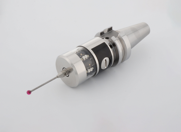
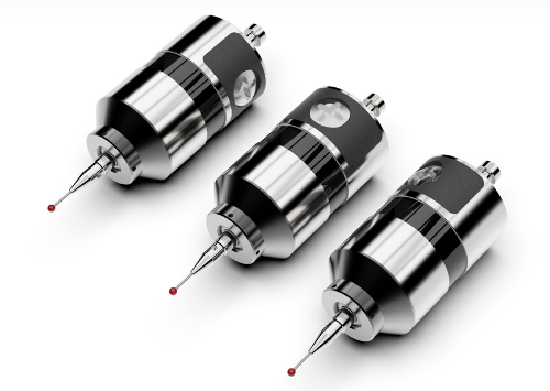
There are two main types of probes used in CMMs. The most common type is the mechanical probe, which physically contacts the object to take measurements. However, modern CMMs may also use non-contact methods such as lasers or cameras that scan the surface of the object to create a “point cloud” of data without touching it. Despite these differences, the fundamental principle remains the same.
The gantry of CMM machines, a framework mounted above the worktable, controls the probe’s movement along the X, Y, and Z axes. It systematically moves the probe to various points on the object’s surface, gathering dimension data. After the probe completes the measurements, the CMM’s computer processes the data to analyze the object’s dimensions and verify its conformity to design requirements.
How to Use a Coordinate Measuring Machine (CMM)?
1. Preparation
Place the object to be measured in the metrology lab for at least 5 hours. This allows the object to reach room temperature (around 20°C), preventing errors caused by thermal expansion.
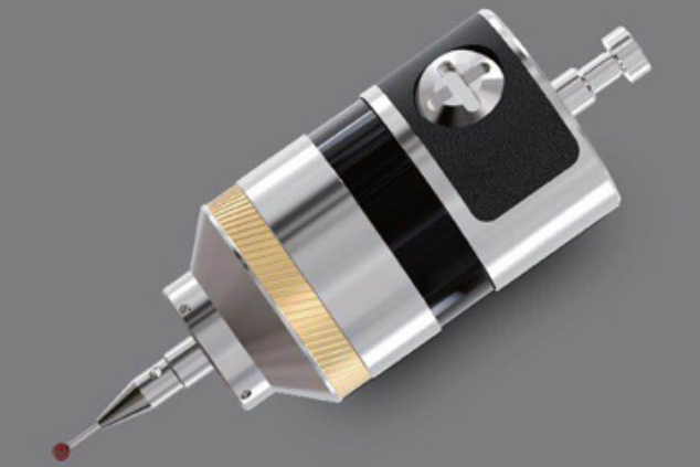
2. Probe Calibration
Before measuring, calibrate the probe (stylus) because the probe tip is spherical, so the machine needs to know the exact center coordinates of the stylus sphere. The diameter of the stylus sphere must be set to calculate the correct contact point offset. Use a reference sphere with a known size and shape to perform this calibration.
3. Setting Coordinates and Alignment
CMMs have a device coordinate system (X, Y, Z axes defined by machine movement directions). The work coordinate system must be aligned with the object’s own reference planes and lines.
To set the work coordinate system, specify:
- A reference plane (which defines the Z-axis perpendicular to it).
- A reference line (usually the X-axis direction; Y is perpendicular to X and Z).
- An origin point (0,0,0), which can be a specific feature on the object (e.g., the center of a hole).
4. Measurement Procedure
Manually or via PC control, move the probe to the desired measurement points on the object. The CMM records the X, Y, Z coordinates of each point touched by the stylus. Each feature, such as planes, lines, circles, cylinders, cones, and spheres, is measured by taking several points. The number of measurement points depends on the element type and the accuracy needed. More points usually mean more accurate results through methods like the least squares fitting.
For 3D shapes without explicit volume (like lines or circles), CMM projects these onto a reference plane to measure correctly. The software calculates dimensions such as lengths, diameters, angles, and geometric tolerances based on these points.
5. Use of Virtual Elements
CMM software can calculate virtual points and lines, such as intersections between two lines or planes and distances between non-physical elements. This function is useful for measuring features that are difficult or impossible to measure with hand tools.
6. Handling Precautions
- Check that all moving parts move smoothly and correctly in their horizontal and vertical directions.
- Always verify machine accuracy using measurement standards.
- Contact the probe with the object at a constant speed to avoid errors.
- Ensure the object’s temperature is stable, or apply temperature correction in the machine settings.
7. Maintenance and Operator Training
Regular maintenance is critical: lubricate, clean, and replace worn parts to maintain accuracy. Proper use requires skilled and trained operators because improper handling can damage the CMM and cause costly repairs. Usually, full-time, trained metrology professionals operate CMMs.
Types of Coordinate Measuring Machine
Before choosing a CMM machine, you need to know about the different types of measuring machines. All CMMs have three orthogonal axes, X, Y, and Z, but in varying structures.
1. Bridge CMM Machine
The bridge-type coordinate measuring machine is the most popular style. The typical 3D bridge CMM machine allows the probe to move along X, Y, and Z, which are orthogonal to each other; each axis has a sensor for monitoring the probe position, usually with micrometer precision. When the probe contacts the object, the machine samples the three sensors, then measures the location of one point on the surface. And repeat the process until generating an area that describes the surface. Bridge machines offer high accuracy and are best suited for medium-sized components.
2. Cantilever CMM Machine
Cantilever machines are usually used for the measurement of relatively small parts and gauges, master parts with their high accuracy and low measurement uncertainty, providing open access to the operator on three sides. The X-axis measuring beam is attached to the side of a rigid structure housing the Y-axis, which limits the size of the X beam. Large support base combined with low weight enables the Cantilever coordinate measuring machine to move fast. The cantilever-type machine also has good capability for automatic loading and unloading.
3. Gantry CMM machine
Gantry-type coordinate measuring machines have a similar structure to a bridge machine, but they’re primarily used to measure large and heavy parts. Most gantry machines are directly mounted on the floor, which is a safe setup that allows the programmer to easily walk up to the part and make the operation more convenient. The operator can access the machine in an unrestricted manner, make small features that can be measured carefully. In addition, the surface plates for smaller components are easily inserted into the gantry machine, decreasing the difficulty of measurement and complexity.
4. Horizontal Arm CMM Machine
Horizontal Arm type machine has a different configuration where a vertical column (X-axis) and a horizontal arm (Z-axis) are mounted on a saddle that runs vertically up and down the X-axis. The Y-axis is the length of a surface plate or a long beam. There are two basic types: plate-mounted and two-runway-mounted. Horizontal arm CMM offers a lower accuracy than the three above CMMs, but it is useful for measuring large surfaces or difficult to reach features, including large thin-walled/sheet-metal type components mounted in fixtures that represent car body position, like a car door.
Application of Coordinate Measuring Machines
Modern coordinate measuring machines can not only complete various kinds of complex measurements under the control of the computer, but also can control the machining by exchanging information with CNC machines, and realize reverse engineering according to the measurement data.
1. CMM in Quality Control
Coordinate measuring machines provide extremely precise size measurements, far more accurate than traditional handheld tools, to ensure that every part matches the original design specifications exactly. CMMs reduce human error by automating the inspection process, producing consistent and repeatable results no matter who operates the machine or when. CMMs also speed up the inspection process significantly. They can measure complex parts quickly using automated routines, reducing inspection time from tens of minutes to just a few. Another key benefit of CMMs in quality control is their ability to standardize measurement across a company. Every part is inspected the same way, creating reliable and traceable digital records that support audits and certifications such as ISO 9001.
2. CMM in Reverse Engineering
In reverse engineering, CMMs help transform physical parts into accurate digital models for further design or manufacturing use. The process starts by preparing the sample part carefully, cleaning it, and securing it in place to ensure precise measurement. Establishing a reference coordinate system is important to guide the scanning path.
Using high-precision probes or laser scanners, CMMs quickly capture detailed 3D data of the part’s surface. This data, often called a point cloud, contains millions of points representing the exact shape of the object. After data collection, specialized software processes the point cloud to remove noise and reconstruct smooth surfaces, converting the raw data into usable digital formats like STL, IGES, or STEP. These digital models can then be imported into CAD software for design modifications, engineering analysis, or CNC programming.
Related Articles:
 Installation Tips Of Workpiece Probe In CNC Machine | CNCLATHING
 Probe Selection Guide & Tips – How To Choose Probe For CNC Machine
 Method For Measuring Trigger Probe In 5 Axis Machining | CNCLATHING
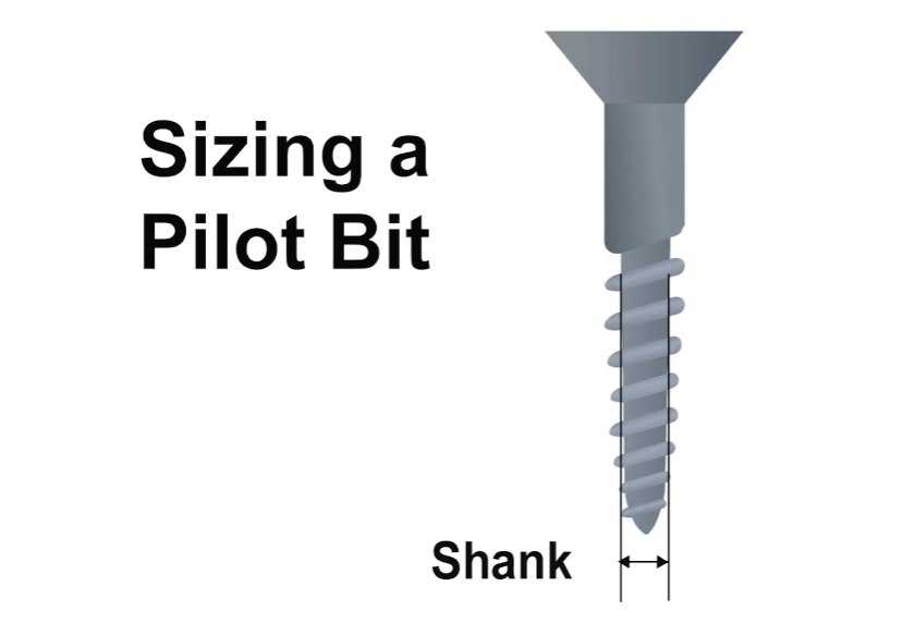 Pilot Hole Drill Bit Size Chart for Wood, Sheet Metal, Lag Screws
 Development Of On-Line Measurement In Wire EDM Machining
 Why Do You Install Probe On CNC Machine – Function & Effect, Advantages Of Probe Installation