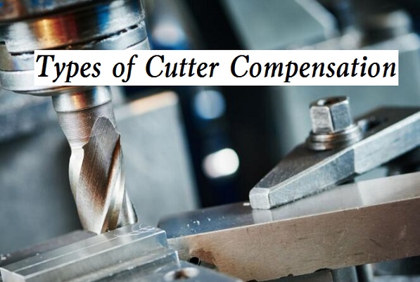
After using the cutter compensation function, you only need to change the tool position compensation value without modifying the CNC program. Below let’s take a look at two different types of cutter compensation methods, they are tool length compensation and radius compensation.
What is Tool Length Compensation?
Tool length compensation is a method by which your CNC control may adjust for variances in the length of different tools, you don’t need to take those differences into account while programming your part. Through the use of tool length adjustment, a CNC machine is able to accommodate a wide variety of tools of varying lengths.
Tool Length Compensation G-Code
The tool length compensation is realized by executing G43 (G44) and H codes. At the same time, we give a Z coordinate value, so that the tool moves to the place where the distance from the workpiece surface is Z after compensation. The other code G49 cancels the G43 (G44). In fact, we do not need to use this command because each tool has its own length compensation.
– G43 represents tool length compensation in the positive direction.
– G44 chooses tool length compensation in the negative direction.
What is Cutter Radius Compensation?
During contour machining, the tool center motion path should offset a certain distance from the actual contour of the part to be machined. This offset is called cutter radius compensation, or tool center offset. Because the CNC system controls the tool center path, the CNC system should calculate the tool center path according to the input part contour size and the tool radius compensation value. According to the tool compensation command, the CNC machine tool can automatically compensate the tool radius. Especially in manual programming, cutter radius compensation is particularly important. In manual programming, the tool radius compensation command can be used to program according to the contour value of the part, without calculating the tool center path programming, which greatly reduces the amount of calculation and error rate. Although using CAD/CAM automatic programming, the manual calculation is small and the program generation speed is fast when the cutter has a small amount of wear or the machining profile size has a slight deviation from the design size, or when the machining allowance changes in each step of rough milling, semi-precision milling and precision milling, an appropriate adjustment is still required. After using the cutter radius compensation, the program is regenerated without modifying the cutter size or modeling size, It is only necessary to modify the cutter compensation parameters properly on the CNC machine tool. It not only simplifies the programming calculation but also increases the readability of the program.
Cutter radius compensation has two compensation forms: B function (Basic) and C function (Complete). As the tool radius compensation of function B is only calculated according to this program, it cannot solve the problem of transition between program segments. The workpiece contour is required to be treated as a fillet transition, so the processability of the sharp corner of the workpiece is not good. Moreover, the programmer must estimate the possible discontinuity and intersection points after tool compensation in advance and handle them manually, which obviously increases the difficulty of programming; The C function tool radius compensation can automatically handle the transition of tool center tracks of two program segments and can be programmed completely according to the workpiece contour. Therefore, modern CNC machine tools almost use C function tool radius compensation. At this time, it is required that at least two subsequent program segments to establish the tool radius compensation program segment must have the displacement code (G00, G01, G02, G03, etc.) specifying the compensation plane, otherwise, the correct tool compensation cannot be established.
Cutter Radius Compensation G-Code
According to ISO, when the tool center track is on the right side of the forward direction specified in the program, it is called right tool compensation, which is represented by G42. Otherwise, it is called left-cutter compensation, which is represented by G41.
– G41 is the left compensation, that is, looking along the tool’s forward direction (assuming the workpiece is still moving), the tool center track is located on the left side of the workpiece contour, which is called left tool compensation.
– G42 is the right compensation, that is, looking along the tool’s forward direction (assuming the workpiece is not moving), the tool center track is located on the right side of the workpiece contour, which is called right tool compensation.
– G40 represents the tool radius compensation off. After using this command, G41 and G42 commands are invalid.
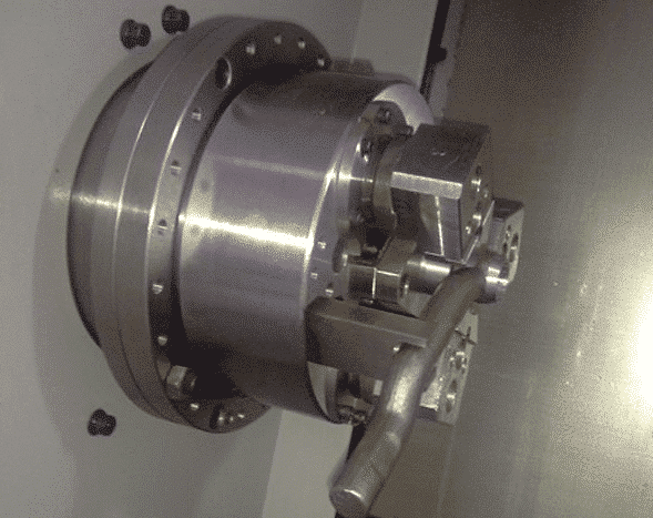
 What is the Compensation Function of CNC Lathing?
 Haas G Codes & M Codes List for CNC Lathe and Mill – Haas & Fanuc G-Code and M-Code PDF Download| CNCLATHING
 CNC Machining Center Vs CNC Mill – Difference Between Machining Center And Milling Machine In Programming
 CNC Machine G-Code Tutorial – List Of G-Codes For CNC Programming | CNCLATHING
 Application Of Error Compensation In Improving Machining Accuracy | CNCLATHING
 Error Compensation For Improving Machining Accuracy Of CNC Machine
