1. The workpiece size is accurate and the surface finish is poor
Fault cause: The tool tip is damaged and not sharp; The machine tool resonates and is placed unsteadily; The machine tool crawls; Poor processing technology.
Solution: If the tool is not sharp after being worn or damaged, regrind the tool or select a better tool to set the tool again; If the machine tool resonates or is not placed stably, adjust the level, lay the foundation and fix it stably. The reasons for mechanical crawling are that the carriage guide rail is severely worn and the lead screw ball is worn or loose. The machine tool should be maintained. After going to and from work, the iron wire should be cleaned and lubricating oil should be added in time to reduce friction; Select the coolant suitable for workpiece processing, and try to select a higher spindle speed when it can meet the processing requirements of other processes.
2. The workpiece has large and small taper head
Fault cause: The placement level of the machine tool is not adjusted well, one high and one low, resulting in unstable placement; When turning a long shaft, the contributing material is relatively hard and the cutting tool is deep, resulting in the phenomenon of tool yielding; The ejector pin of tailstock is not concentric with the main shaft.
Solution: Use the level to adjust the levelness of the machine tool, lay a solid foundation, fix the machine tool and improve its toughness; Select a reasonable process and appropriate cutting feed to avoid the tool being forced to yield; Adjust the tailstock.
3. The workpiece size differs from the actual size by a few millimeters, or there is a great change in an axial direction
Fault cause: The speed of fast positioning is too fast, and the drive and motor cannot react. After long-term friction loss, the mechanical carriage screw rod and bearing are too tight and stuck; The tool holder is too loose and cannot be locked after changing the tool; The editing program is wrong, and the head and tail end are not echoed or the cutter compensation is not cancelled; The electronic gear ratio or step angle of the system is set incorrectly.
Solution: If the fast positioning speed is too fast, properly adjust the go speed, cutting acceleration and deceleration speed and time to make the driver and motor work normally under the rated operating frequency; If the carriage and screw crane bearings are too tight and stuck after the machine tool is worn, they must be readjusted and repaired.
If the tool holder is too loose after tool change, check whether the reversing time of the tool holder is met, whether the worm and worm inside the tool holder are worn, whether the clearance is too large, whether the installation is too loose, etc; If it is caused by the program, it is necessary to modify the program, improve it according to the requirements of the workpiece drawing, select a reasonable processing process, and write the correct program according to the instructions of the manual.
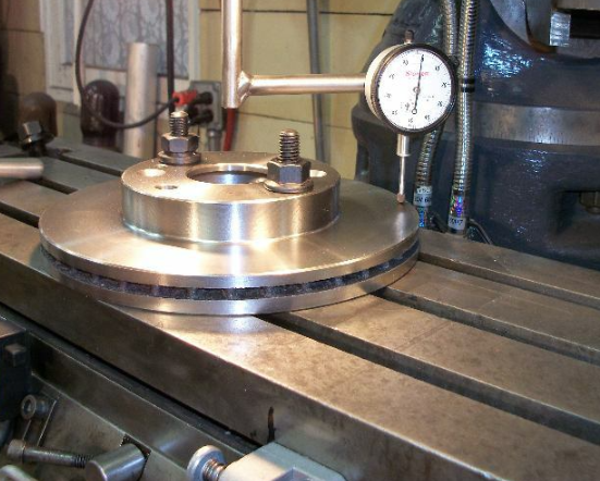
If the size deviation is too large, check whether the system parameters are set reasonably, especially whether the parameters such as electronic gear and step angle are damaged. If this phenomenon occurs, it can be measured by playing a dial indicator.
4. The arc processing effect is not ideal and the size is not in place
Fault cause: Resonance caused by overlapping vibration frequencies; Processing technology; Unreasonable parameter setting and excessive feed speed make the arc machining out of step; Looseness caused by large screw clearance or out of step caused by too tight screw; The timing belt is worn.
Solution: Find out the parts that produce resonance, change their frequency and avoid resonance; Considering the processing technology of workpiece materials, reasonably compile the program; For stepper motor, the processing rate f cannot be set too large; Whether the machine tool is installed firmly and placed stably, whether the carriage is too tight after wear, the gap increases or the tool holder is loose; Replace the timing belt.
6. The processing of one process of the workpiece changes, and the dimensions of other processes are accurate
Fault cause: Whether the program parameters of this program section are reasonable, whether they are within the predetermined track, and whether the programming format meets the requirements of the manual.
Solution: In case of disordered teeth and wrong pitch in the thread program section, it is immediately associated with the peripheral configuration (encoder) of thread processing and the objective factors of this function.
7. Each process of the workpiece has the phenomenon of increasing or decreasing
Fault cause: Programming error; Unreasonable system parameter setting; Improper configuration setting; The mechanical transmission parts have regular and periodic changes and faults.
Solution: Check whether the instructions used in the program are executed according to the required track specified in the instruction manual. You can judge by playing the dial indicator. Locate the dial indicator at the starting point of the program, let the carriage return to the starting point after the program is completed, and then repeat the execution, even if you observe the results and grasp the law;
Check whether the system parameters are set reasonably or considered to be changed; Whether the single calculation on the coupling parameters of the connection calculation of the relevant machine tool configuration meets the requirements and whether the pulse equivalent is accurate; Check whether the transmission part of the machine tool is damaged, whether the gear coupling is uniform, and whether there are periodic and regular faults. If so, check the key parts and eliminate them.
8. Dimensional changes caused by the system are unstable
Fault cause: Unreasonable system parameter setting; Unstable working voltage. The system is subject to external interference, resulting in system out of step; Capacitance has been added, but the impedance between the system and the driver does not match, resulting in the loss of useful signals; Abnormal signal transmission between system and driver; System damage or internal failure.
Solution: Whether the speed and acceleration time are too large, whether the spindle speed and cutting speed are reasonable, and whether the operator’s parameter modification leads to the change of system performance; Install voltage stabilizing equipment; The grounding wire shall be reliably connected, and anti-interference absorption capacitance shall be added at the pulse output contact of the driver.
Select appropriate capacitor model. Check whether the signal connecting line between the system and the driver is shielded, whether the connection is reliable, and whether the system pulse generation signal is lost or increased; Send to the factory for repair or replacement of the main board.
9. What if the workpiece displacement affects the accuracy
Fault cause: When machining the above workpieces on the three-axis CNC machining center, there are sometimes problems such as the internal structure position movement of the machined workpieces and the out of tolerance of dimensional accuracy. The causes of these problems are often caused by the low secondary clamping and alignment accuracy,
Solution:
1) Lever dial indicator method
The lever dial indicator method is to suck the lever dial indicator on the spindle of the CNC machining center, make the dial indicator close to the horizontal position, then lower the dial indicator to the fine reference plane to be corrected, move the worktable through the pulse handwheel of the CNC numerical control system, and rotate the spindle by hand to make the dial indicator press to the fine reference plane and show the maximum value for workpiece adjustment. At the same time, the relative coordinate values in the relevant directions of the CNC system of the CNC machining center are cleared.
2) Cushion block method
The cushion block method requires the use of auxiliary tools such as standard cushion blocks to translate the fine datum plane of the workpiece. Put a standard cushion block between the tool setting instrument and the workpiece, install a photoelectric edge finder on the spindle of the CNC machining center, rotate the spindle at low speed, and the photoelectric edge finder directly touches the left and right cushion blocks. The secondary difference is the error value. Adjust the workpiece according to this difference. However, due to the gap between the cushion block and the workpiece, this method is not as accurate as using the lever dial indicator.
The above is the solution to the problem of machining accuracy when machining parts in CNC machining center. We hope it will help you.
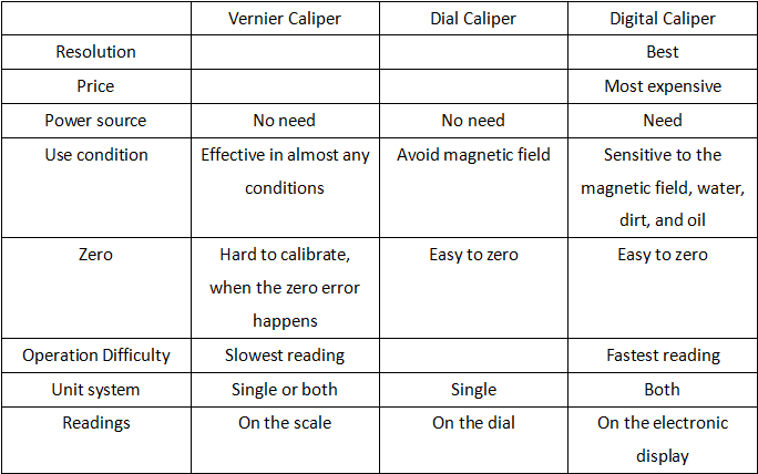 Dial vs. Digital vs. Vernier Caliper, What’s the Difference Between Them? | CNCLATHING
 Tramming a Milling Machine Head: Tools, Methods, Process & What is Tramming | CNCLATHING
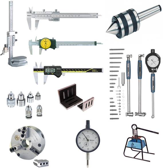 Must Have Machinists Tools | Essential Machine Shop Tools List | CNCLATHING
 How To Deal With Failures Of CNC Machine | CNCLATHING
 CNC Machine Block Diagram: Systems & Components (Parts) of CNC Lathe Machine
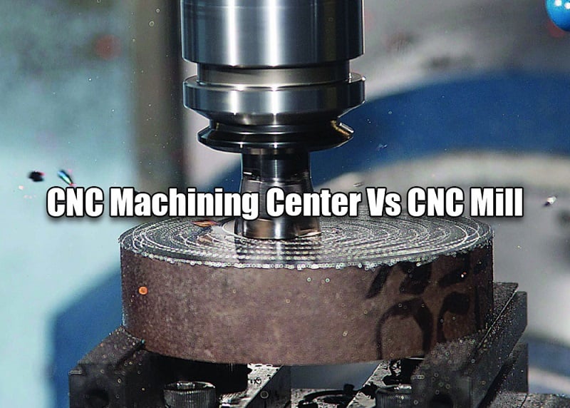 CNC Machining Center Vs CNC Mill – Difference Between Machining Center And Milling Machine In Programming
