1. Feed drive system
The feed drive system is divided into DC feed drive and AC feed drive. The failures can be roughly divided into three categories. One is to display alarm information on CRT by using the diagnostic program of software; Second, the hardware on the speed control unit (LED indication, fuse fusing, etc.) is used to display the alarm; Third, there is no fault with any alarm indication.
2. Software alarm form
This kind of alarm is displayed on the CRT through the monitoring and alarm of the feed drive by the system. The first case is the error alarm of the servo feed system; Most of these alarms are caused by faults in speed control, or failures in parts related to position control or servo signal of NC; The second case is the fault caused by the relevant detection elements (speed measuring motor, resolver or pulse encoder); The third case is the alarm about overheating, such as servo unit, transformer and motor.
3. Hardware alarm form
Including alarm indicator light and fuse fusing on speed control unit, tripping of various switches (for protection), etc. The meaning of alarm indicator varies with the design of speed control unit. Generally, there are the following situations:
① high voltage alarm. The reason for this kind of alarm is generally that the input AC power supply voltage exceeds 10% of the rated value or the insulation capacity of the motor decreases. A megger can be used to measure the insulation capacity of the motor.
② High current alarm. This kind of alarm is mostly due to the damage of the power driving element thyristor module or transistor module on the speed control unit. In case of power failure, use a multimeter to measure the resistance between the collector and emitter of the module. If it is less than 10 Ω, it indicates that the module has been damaged.
③ Low voltage alarm.
④ Overload alarm. The reason for this kind of alarm is that the mechanical load is abnormal, or the upper limit of motor current on the speed control unit is set too low, and there are many mechanical loads, which are seriously worn due to the long service time of the equipment. The setting value of the current can be changed.
⑤ Speed feedback alarm. This kind of alarm is mostly caused by poor speed or position feedback line of servo motor or poor contact of connector. It may also be the problem of feedback signal processing module in NC.
⑥ The fuse burns out or the circuit breaker trips. There are many reasons for this kind of alarm, which must be determined according to the specific situation. If the alarm still occurs after replacing the fuse, the cause of fusing must be found.
⑦ Protection switch action. If this kind of alarm is an obvious protection switch action, the reason is also very simple. Repeat the operation to avoid it, such as travel switch. If the transformer is overheated and the air switch trips, it is necessary to find out the cause. Some are caused by the set value problem, and some are caused by overheating in the processing process.
⑧ Failure without alarm display. Such failures include machine tool vibration, machine tool out of control, excessive machine tool noise, etc. in case of such situations, comprehensive consideration shall be made and judgment shall be made according to the actual situation.
 CNC Machine Installation Tips – How To Assemble & Install CNC Machine Tools The Right Way
 How To Make CNC Machine Work Stably For A Long Time – Tips To Expand CNC Machine Life
 Types & Classification Of CNC Machine Tools | Basics Of CNC Machining
 Maintenance Of Turning Milling Compound CNC Machine Tool
 Advantages Of Automatic Lathe Processing And Daily Maintenance
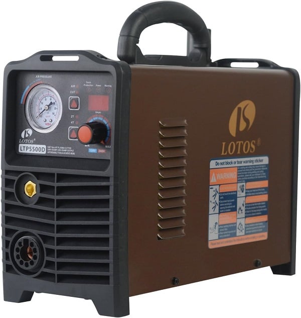 Best Budget Plasma Cutter – Top 10 Cheap Plasma Cutters Under $500/1000
