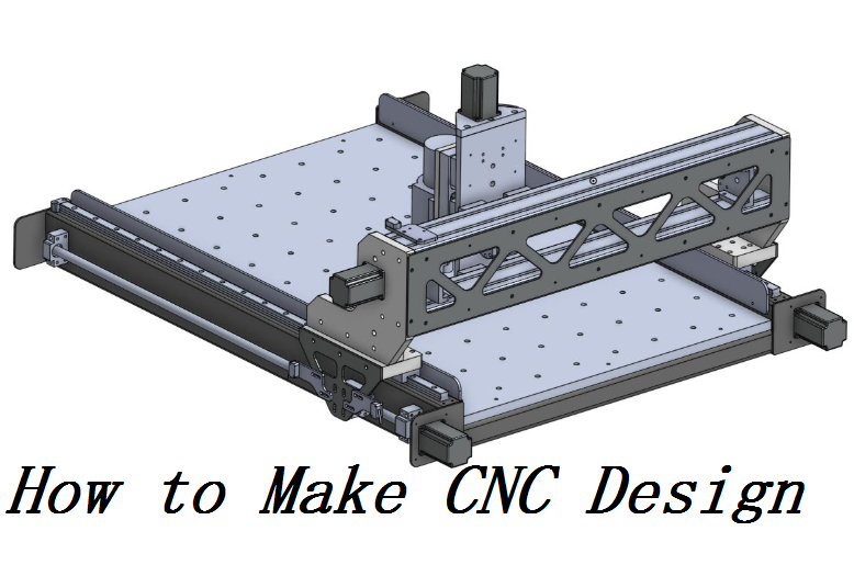
Before designing a part for CNC, there are some tips you can master to speed up the process and avoid lots of problems.
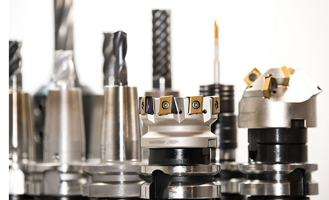
1. Consider the geometry of the cutting tool used to remove material in the machining and features you designed should fit the processing method of the CNC machine.
2. When designing a part with Scan2CAD, remember to define the scale of your vector image, the system units can be set as millimeters. Reduce the vector lines to the lowest number of nodes and only export drawing parts into the final DXF file. Convert splines and arcs, remove spaces and draw one coherent cut path. Delete duplicate copies of objects.
3. Cavity depth should be under four times the tool diameter in order to reduce the machining difficulties and possibility of tool breakages.
4. Engraved text is better than embossed text because it reduces the waste of material and small features should be avoided.
5. Try not to use specific tolerances, because when requiring higher accuracy, more time and labor will be needed and causes increased cost.
6. In CNC programming, all the dimensions and positions of points, lines and surfaces are based on the programming origin. Therefore, it is better to mark the coordinate dimension directly on the part drawing, or use the same datum to introduce dimension as much as possible.
7. The conditions of geometric elements should be complete and accurate in programming.
8. In CNC machining, the working procedure is often concentrated, so it is very important to locate the same datum. It is often necessary to set some auxiliary benchmarks.
 Top 12 CNC Machining & Programming Experiences | CNCLATHING
 Top 10 Best AI for CNC Machining Program, CAM/CDM Design, G-Code Generate (Free & Paid)
 CNC Machining Center Vs CNC Mill – Difference Between Machining Center And Milling Machine In Programming
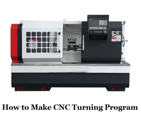 CNC Lathe Programming Guide & Tips – How to Make CNC Turning Program | CNCLATHING
 CNC Machine Block Diagram: Systems & Components (Parts) of CNC Lathe Machine
 CNC Machining Vs Conventional Machining – Difference Between CNC Machining And Conventional Machining
