Proper cutting speed and feed settings are the basis of efficient operation on CNC machines. In this article, let’s learn about speeds and feeds selection, calculation, and more. Check out how to determine cutting speed and feed rate.
What are Speeds and Feeds? – Difference Between Cutting Speed and Feed
Speeds and feeds are two separate velocities – cutting speed and feed rate in machining, but they have a combined effect on the cutting process, determining the rate of material removal, surface finish, and power requirements.
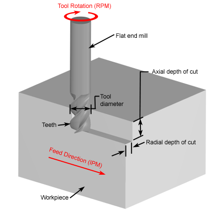
Cutting speed, also called surface speed, is the relative velocity between the cutting tool and the surface of the workpiece being cut. The feed rate is the relative velocity at which the cutter is advanced along the workpiece, or defined as the distance of tool travels during one spindle revolution.
Cutting Speed Factors & How to Determine Cutting Speed?
Cutting speed may also be defined as the rate at which the part surface, that is, how fast the material moves past the cutting edge of the tool. For different operations, the definition of surface may vary. In drilling and milling, the surface is the outside diameter of the tool. In turning and boring, the surface can be defined on either side of the depth of cut (the starting surface or end surface). Cutting speeds are expressed in feet per minute (imperial) or meters per minute (metric).
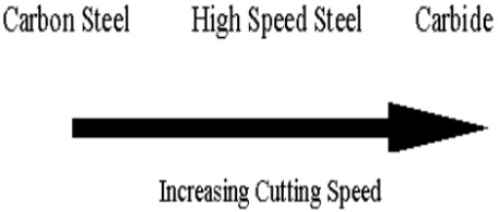
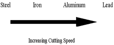
The material to be machined and the cutting tool materials will have a large impact on the calculation of cutting speed. The depth of the cut and the feed rate will also affect the speed, but not as greatly as the component hardness. The optimum cutting speed will be different if the types of material and machining conditions are changed. The softer the material of the workpiece, the higher the cutting speed. When the cutting tool material is stronger, the cutting speed increases.
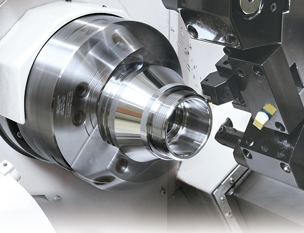
On a rotary tool like a drill bit or milling cutter, cutting speed is equal to how fast its periphery spins relative to the stock clamped to the worktable. It’s the same with the tools used on lathes, except their cutting speeds are measured by how fast the rotary material moves past the edge of the turning tool. What’s the recommended cutting speed for different materials? Check out the Cutting Speed Chart for turning, drilling, and more CNC machining operations when processing a wide range of metals.
Feed Rate Selection – How to Determine Feed Rate on Lathe
The feed of a lathe is determined by the speed of the lead screw or feed rod. The speed is controlled by the change of gears in the quick-change gearbox. For rough cutting, the goal is only to remove excess materials from the stock; a coarse feed should be applied. For finishing cuts, a good surface finish is important, and the process should complete the size of the machining parts; a fine feed should be adopted. For general CNC turning using an HSS cutting tool, a feed rate of .005–.020 inches per revolution for roughing and .002–.004 inches per revolution for finishing is recommended.
How Do You Calculate Cutting Speed and Feed?
When calculating the cutting speed in meters per minute, the spindle speed of the machine (n) and the diameter of the part must be known. When calculating the feed rate, the spindle speed, feed per tooth, and the number of flutes should be known.
Calculator: Milling Speed and Feed Calculator
Turning Speed and Feed Calculator
Drilling Speed and Feed Calculator
Cutting Speed and Feed Rate Formula
Cutting Speed: Vc = (π* D * n)/1000
Feed: Vf = n * fz * Z
Vc: cutting speed (m/min)
π: 3.14
D: diameter (mm)
n: spindle speed (min-1)
Vf = feed (mm/min)
fz = feed per tooth (mm/tooth)
Z = number of flutes
Setting Speeds on a Lathe Machine
Too high a cutting speed will make the tool more easily damaged, while too low a speed may result in loss of time and reduced production efficiency. How to set the cutting speed on a lathe?
– When speeds are measured in revolutions per minute, they are changed by stepped pulleys or gear levers.
– For belt-driven lathes, speeds are obtained by changing the flat belt and back gear drive.
– For a geared-head lathe, speeds are changed by moving speed levers into proper positions according to the r/min chart fastened to the headstock. But don’t change the speeds when the machine is running.


