
A cutting speed that is too low or too high will harm the quality of machined parts and the life of tools in CNC manufacturing. How to set the best SFM in machining? In this article, we’ll dive into the SFM meaning and definition from the full form, its calculation formula, the conversion between RPM and an SFM chart for different machining processes, and cutters.
What Is SFM in Machining – SFM Full Form and Meaning
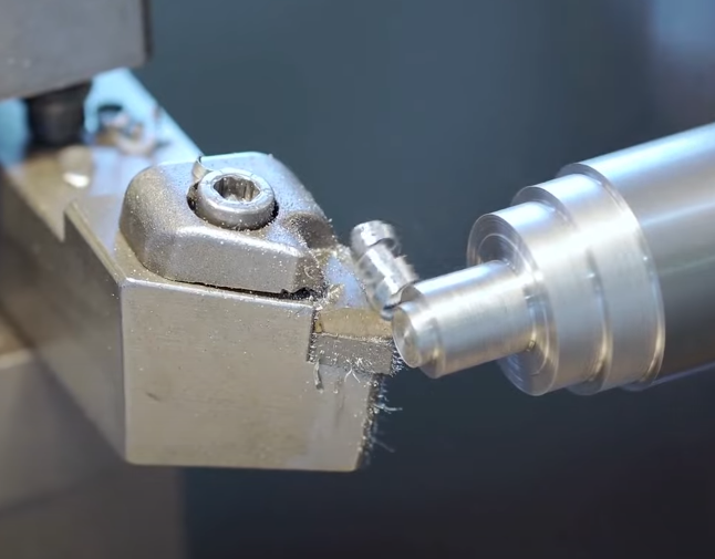
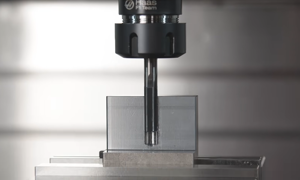
In CNC machining, the full form of SFM is Surface Feet per Minute, so it is also known as SFPM. SFM is a combination of surface speed and the unit feet per minute that defines the relative linear velocity between the cutting edge of a tool and the workpiece, not the rotational speed. SFM is a common unit of measurement for cutting speed in machining and is primarily used in the United States, while other countries typically use meters per minute. In milling operations, the workpiece remains stationary while the spindle rotates the milling cutter; the spindle’s rotational speed, measured in RPM (Revolutions per Minute), is converted into cutting speed based on the diameter at which the cutter contacts the workpiece. Conversely, in turning operations, SFM is calculated differently as it relates to the rotational speed of the workpiece itself.
Why Is SFM Speed Important?
If the SFM is too high, it can lead to excessive heat generation, rapid tool wear, degraded surface finish, and potential material deformation due to thermal expansion. However, if the SFM is too low, it can result in poor material removal rates, increased tool pressure, potentially causing breakage, heat buildup due to rubbing rather than efficient cutting, and surface finish issues stemming from inadequate cutting action or tool chatter.
What Is Surface Speed in Machining (Measurement and Conversion)?
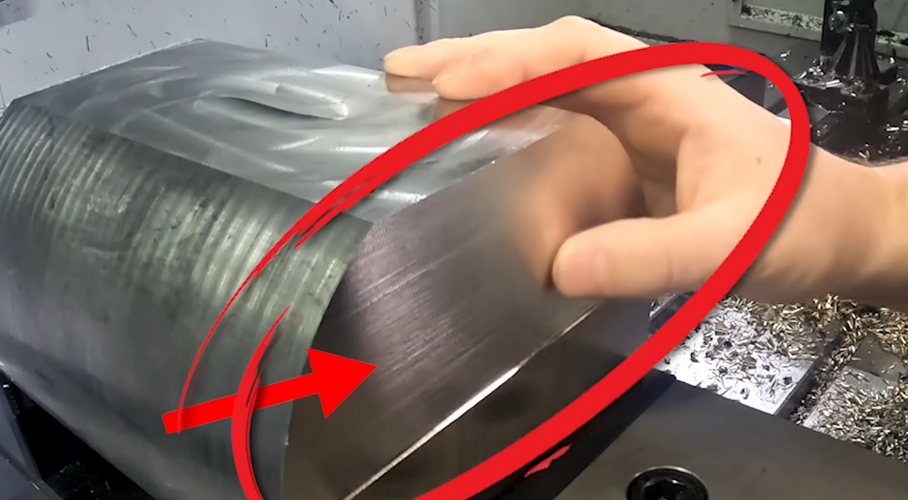
Surface speed describes how fast the cutting edge of a tool moves across the material being worked on in CNC machining. It tells us the speed at which the tool’s surface slides over the workpiece, which is important for making clean cuts and avoiding tool damage. SFM is simply one of the standard measurements of this speed in feet per minute, commonly used in countries with imperial units. So surface feet per minute is also known as SFPM. In places using the metric system, surface speed is often shown in meters per minute (m/min) or millimeters per minute (mm/min). Two units can also be converted to each other; the formula is 1 ft/min = 304.8 mm/min.
How to Calculate SFM in Machining – SFM Formula and Calculation
The SFM calculation formula is Surface Feet per Minute (SFM) = (RPM x Circumference) / 12. But the circumference is different in CNC milling and CNC turning. In the turning process, it refers to the workpiece circumference, while for milling operations, the cutter circumference is required. So here are two SFM formulas to use:
- Milling SFM = (RPM x Tool Diameter) / 3.82
- Turning SFM = 0.262 x Part Diameter x RPM
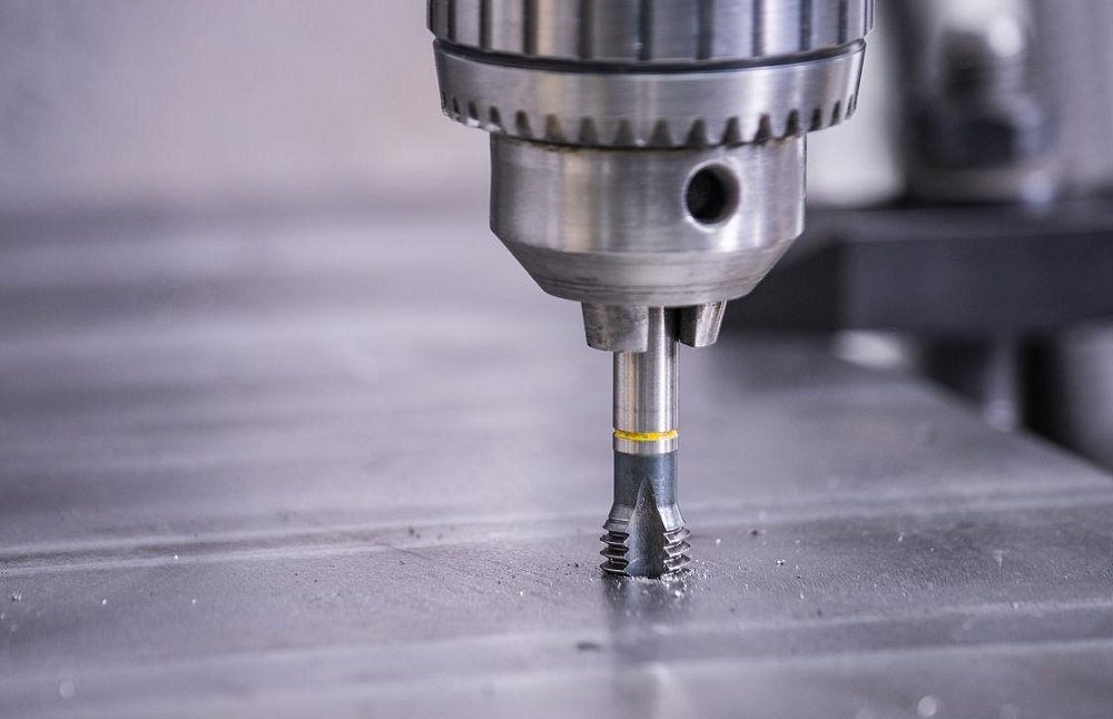
Another form of the SFM formula is (π × D × RPM) / 12, where D is the diameter of the cutting tool or stock in inches, RPM is the rotational speed of the spindle (revolutions per minute), π is constant pi (approximately 3.14159) and 12 is the conversion factor to convert inches to feet. In drilling, make sure to use the drill diameter. Our CNC speed and feed calculator can help you get the SFM and RPM results for turning, milling, and drilling operations accurately and quickly.
Difference Between RPM and SFM
RPM stands for Revolutions Per Minute and tells us how many times the tool spins around in one minute. It’s like counting how many full circles a wheel makes in a minute. On the other hand, SFM means Surface Feet Per Minute, and it measures how fast the edge of the cutting tool moves across the material’s surface. Instead of counting spins, SFM tells us the actual speed of the cutting edge sliding over the workpiece.
These two are closely connected, but the connection depends on the size of the tool. When a tool spins, the bigger it is, the farther its edge travels in one spin. So at the same RPM, a bigger tool will have a higher SFM because its edge covers more distance. Conversely, a smaller tool’s edge travels less distance per spin, resulting in a lower SFM for the same RPM. This means if you change the tool size, you also need to change the RPM to keep the right cutting speed, or SFM, to work well. When setting up a machine, you usually enter RPM because that’s what the machine understands; it controls how fast the tool spins. But machinists and software often start by figuring out the ideal SFM based on the material and tool type. Then, they use a formula that includes the tool diameter to convert that SFM into the right RPM setting for the machine. This process helps make sure the cutting is smooth and efficient.
SFM to RPM Conversion Formula in Different Machining Processes
The basic SFM to RPM formula is RPM = SFM/Circumference. Considering the diameter and unit difference, the actual calculation is as below in different processes.
- Milling: RPM = 12 x SFM / Tool Diameter x π
- Turning: RPM = 12 x SFM / Workpiece Diameter x π
- Drilling: RPM = 12 x SFM / Drill Diameter x π
RPM to SFM Conversion Formula in Different Machining Processes
SFM = RPM x Circumference
- Milling: SFM = RPM x Tool Diameter x π / 12
- Turning: SFM = RPM x Workpiece Diameter x π / 12
- Drilling: SFM = RPM x Drill Diameter x π / 12
Material SFM Chart for Milling, Turning and Drilling
If you are not sure about the surface feet per minute for different materials, here is a chart with typical SFM values for common materials used in different machining processes with two types of cutting tools. The cutting speed of different grades of the same material will vary; machining material hardness, machinability, thermal properties, tool geometry, tool material, and tool coating will affect the final SFM.
| Material | Milling | Drilling | Turning | ||||||||
| HSS Cutter (ROU.) | HSS Cutter (FIN.) | Carbide Cutter (ROU.) | Carbide Cutter (FIN.) | HSS Drill | Carbide Drill | HSS Tool (ROU.) | HSS Tool (FIN.) | Carbide Tool (ROU.) | Carbide Tool (FIN.) | ||
| Cast Iron | Malleable | 90 | 100 | 315 | 490 | 70 | 245 | 130 | 150 | 300 | 450 |
| Machine | 60 | 70 | 210 | 325 | 50 | 175 | 90 | 110 | 210 | 315 | |
| Medium Hard | 30 | 40 | 105 | 160 | 25 | 85 | 45 | 50 | 100 | 150 | |
| Hard | 15 | 20 | 55 | 80 | 12 | 40 | 22 | 25 | 50 | 75 | |
| Steel Castings | 45 | 55 | 155 | 240 | 35 | 120 | 65 | 80 | 150 | 210 | |
| Steel Up to 0.3% C. | Soft | 90 | 110 | 315 | 490 | 70 | 245 | 130 | 160 | 300 | 440 |
| Medium | 60 | 70 | 210 | 325 | 50 | 175 | 90 | 100 | 210 | 315 | |
| Hard | 40 | 50 | 140 | 215 | 30 | 105 | 50 | 65 | 115 | 175 | |
| Tool Steel, annealed | 40 | 50 | 140 | 215 | 30 | 105 | 50 | 65 | 115 | 175 | |
| Cr. Ni. Steel, annealed | 40 | 50 | 140 | 215 | 30 | 105 | 50 | 65 | 115 | 175 | |
| Brass | 350 | 450 | 1200 | 1800 | 120 | 420 | 350 | 455 | 1200 | 1550 | |
| Bronze | 300 | 390 | 1050 | 1550 | 100 | 350 | 300 | 390 | 1050 | 1350 | |
| Aluminum | 700 | 900 | 2400 | 3100 | 425 | 1400 | 750 | 975 | 2600 | 3300 | |
Related Articles:
 CNC Tapping Speeds and Feeds Chart, Formula, Calculator (Metric/Imperial)
 Carbide & HSS Reamer Speeds and Feeds (RPM) Chart in Metric
 Sprocket Types & Size Chart (Pitch Diameter, Specs, Uses, Design) | Chain Sprocket Catalogue
 How To Reduce & Stop Chatter Vibration in CNC Milling/Turning/Drilling/Grinding Lathe?
 How to Calculate CNC Machining Time – CNC Machining Cycle Time Calculation | CNCLATHING
 Top 12 CNC Machining & Programming Experiences | CNCLATHING