- Home
- Machining techniques
- CNC Machining Services
- Cooperative supply services
- Designs
- Materials
- Finishing Services
- Shop
- Products
- Guide
- About Us
- Contact Us
2021.1.28
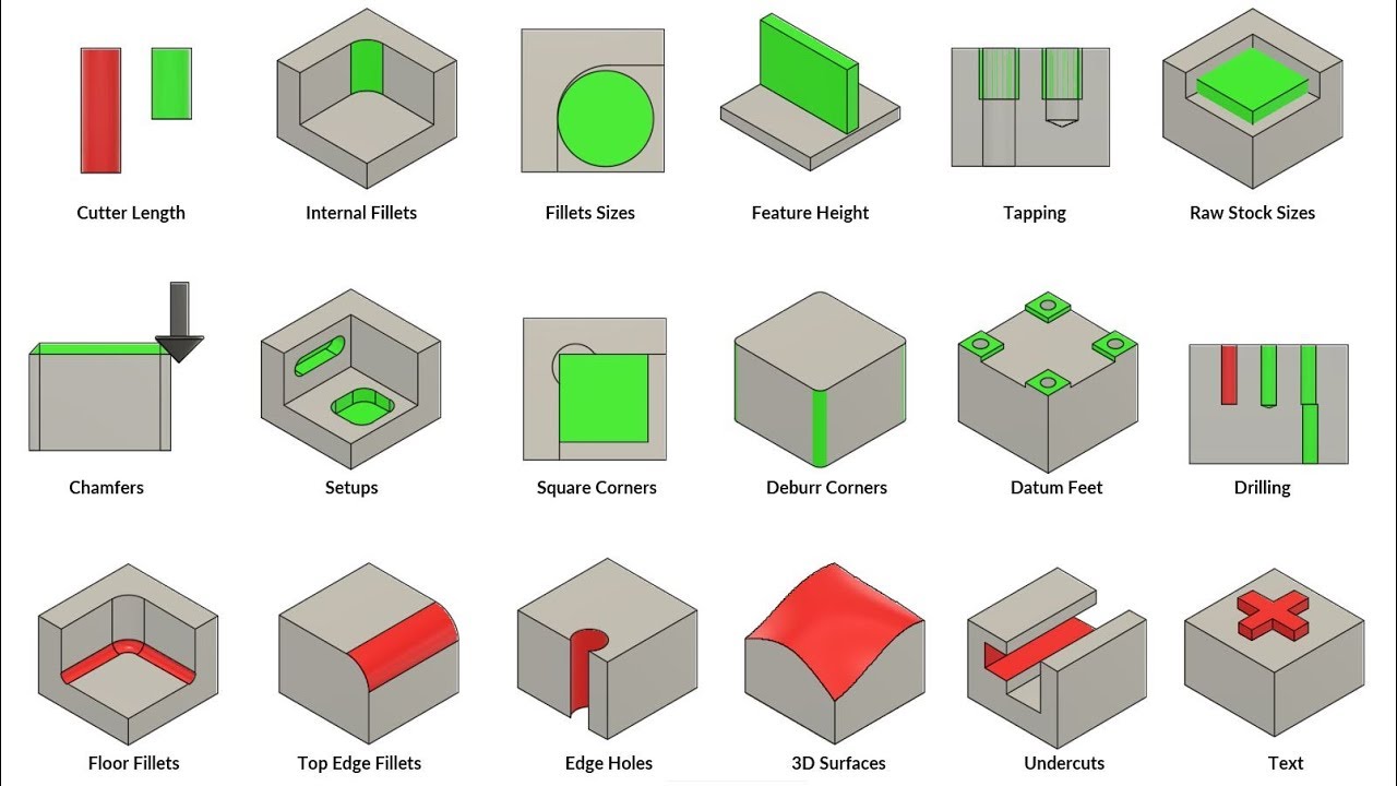
In this tutorial, we will go over some of the top tips and tricks on how you can improve your designs and decrease cost while optimizing for manufacturing on a CNC milling process. We’ll cover everything from fillets, tapping, chamfers, setups, drilling, undercuts, and even text.
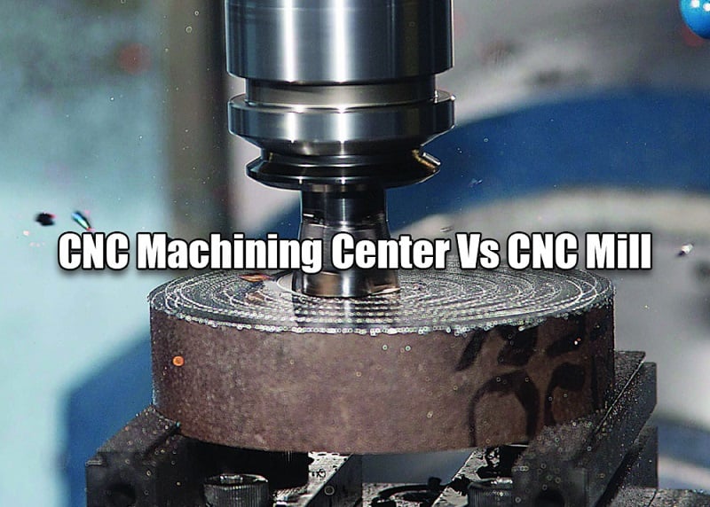
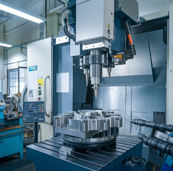
A CNC milling machine is used to transform blocks of raw stock into finished parts by cutting away material in a subtractive manufacturing process. They are generally three axes to a milling machine. The x-axis, which is left in right movement; the y-axis, which is forwards in backward movement; and the z-axis, which is up-and-down movement. these three axes of motion let the spindle, which spins a cutter at very high speeds, carve away material and leave behind nearly any shape desired. The part being milled is held in a vise, which is in turn attached to the table of the CNC. There are more advanced machines with additional features and axes, but understanding the simple three-axis milling machine is an important first step to mastering manufacturing.
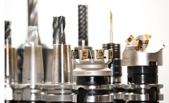
#1 Types Of Cutters
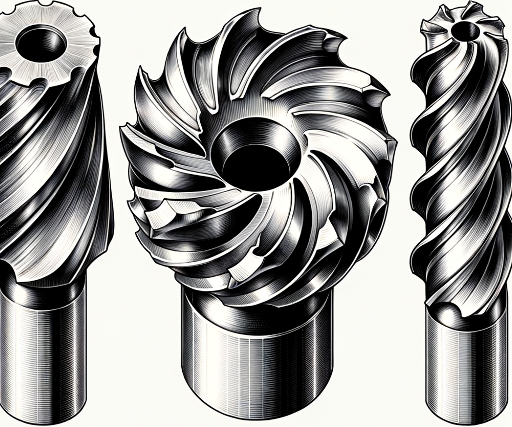
There are many countless types of cutters in the world of CNC machining. Understanding the most basic types provides the knowledge needed to design better parts.
-1- The flat end mill is the most common end mill, it produces a flat-bottom cut that is useful for material and finishing of vertical walls.
-2- The bullnose end mill is similar to the flat end mill, but with very small radii in the corner that increases tool strength by eliminating thin tips. good for fast material removal, and leave a small bottomed radius on parts.
-3- The ball end mill is good for surfacing complex 3D shapes as well as machining larger bottom floor radii.
-4- The drill is only useful for making vertical holes in parts. cutters with the shortest length and largest diameter are preferred.
An end mill is effectively a cantilever beam. Every doubling of a mill length for the same diameter, increases the deflection by eight times, requiring significantly slower machining times. From an alternative viewpoint, having the diameter of the end mill for the same length will increase deflection by 16 times. Two end mills with the same force applied, but the one with twice as long has more deflection than the other one.
#2 Part Design
This carries into the part design, where the designer should always be thinking of the length of the end mill that is needed to machine the feature drawn.
-1- Short end mills with a large diameter will give the fastest machining time, which will result in the most cost-effective part.
-2- Internal fillets should be as large as possible. This allows a large diameter tool to be used, which will decrease machining time. As a rule of thumb, the radius should be less than one-third of the height. So a 12-millimeter deep pocket should use at least a four-millimeter internal radius. It is possible to have smaller internal fillets, but the part cost will increase accordingly.
-3- Know the size of the tooling you’re using and always keep the internal fillet radii slightly larger. This keeps the tool from rapidly increasing the amount of material it’s cutting when it makes it to the corner. If the tool diameter exactly matches the internal fillets, then as the tool enters the corner, it will suddenly switch to a huge amount of cutting engagement momentarily, which could cause the cutter to break. For example, if the tool being used is a 10-millimeter diameter end mill, make the park corner fill a little bit bigger say six millimeters.
-4- If a square corner is a must for a mating part then use a dog bone corner, keep the diameter of the circular corner cut as large as possible.
-5- Keep the height of machine features less than four times their width. Tall and skinny features will vibrate significantly during machining, causing poor tolerances and surface finishes. Try and add reinforcement where possible to reduce tall isolated features.
-6- For tap holes, a through-hole is always preferred to a blind hole. As it allows the chips from the cutting threads to be evacuated. Don’t tap a hole any deeper than three times the diameter. There isn’t any increase in strength past this point. It just gets more difficult to manufacture and to thread in the fastener.
-7- For blind holes, always allow the pilot drill to extend past the threads by half the diameter. It is difficult to tap threads all the way to the very bottom of the hole and requires the machine is to change out the tap type to achieve this.
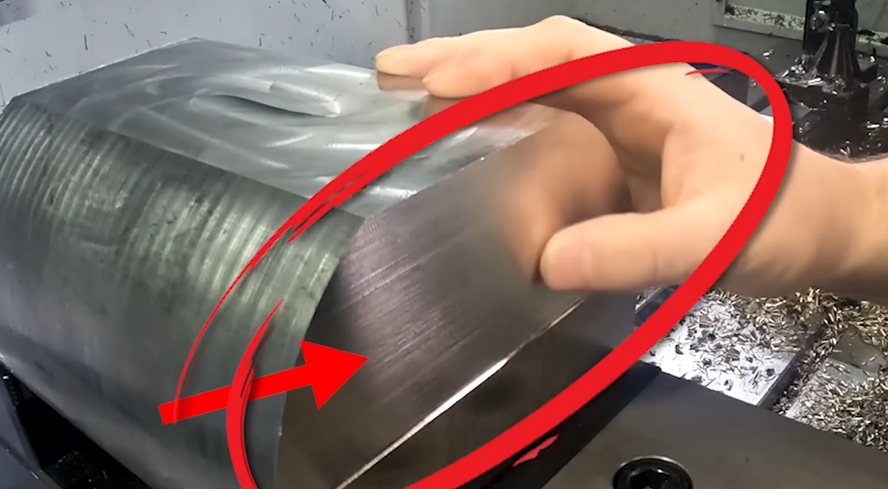
-8- Make sure your finished parts fit inside of off-the-shelf raw stock dimensions. Check your metal supplier for common sizing. Always leave three millimeters below the part for the device to grip the part with and at least one millimeter all the way around. This leaves some material to be machined off, so you’re always left with a machined surface that looks good and is dimensionally accurate.
-9- If you want the sharp edge broken on a part, simply point to it on the drawing and label it as a broken edge. The machinist will deeper this edge, only model a chamfer if you actually need a specific dimension. Keep the angle of a chamfer as 45 degrees, as this is a very common tool size. Different widths of the chamfer can be made with the same tool simply by positioning it in a different location.
-10- Every time the part is clamped to the vise and located. This is known as a setup. Reducing the number of setups decreases machine time, which makes the part more cost-effective.
-11- Reducing the number of setups increases part accuracy. As features made in the same setup are made nearly as accurate as the CNC is made, which is quite good. Since all tool paths must originate with a spinning cutter coming from the vertical direction, any features on the side of the part required the part to be removed from the vise and re-clamped. Re-clamping takes time and introduces an opportunity for error since the part must be located in the vise again for the program to continue cutting.
-12- Always add small fillets to all external corners. There free features for CNC milled parts. Any radius will work. This type of fillets doesn’t drive any tooling, due to the filler being on an outside corner. This will reduce sharp edges and eliminate weak corners that could easily scratch or damage other components during assembly.
-13- If very high flattest tolerances are needed, utilize small bosses with the reduced area. Especially on larger parts, this allows only certain areas to need high tolerances. The rest can be held much looser. This way the machine part can be easily tuned to meet the required tolerances.
That’s all the CNC machine parts designing guide and click HERE to see more information on how to design parts for fillets, tapping, chamfers, setups, drilling when CNC machining.
 Face Mill vs Shell Mill vs End Mill Cutters: Differences & When To Use Each Milling Cutter?
 CNC Machining Center Vs CNC Mill – Difference Between Machining Center And Milling Machine In Programming
 Top 12 CNC Machining & Programming Experiences | CNCLATHING
 How To Reduce & Stop Chatter Vibration in CNC Milling/Turning/Drilling/Grinding Lathe?
 Why Choose China CNC Machining and How to Find the Best CNC Machining Manufacturer
 CNC Machine Block Diagram: Systems & Components (Parts) of CNC Lathe Machine
