
In addition to cylindrical grinding, there is another grinding process is surface grinding, which is also the most common type. To get the best manufacturing practices, here we’ll break down the surface grinding process, machine, types, parts, diagram and comparison between surface grinders and milling machines.
What Is Surface Grinding?
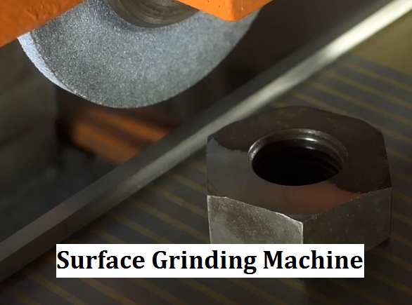
Surface grinding is a widely used abrasive machining process in industrial applications for producing flat surfaces on workpieces. Classified under DIN 8589-11 as a face-peripheral-longitudinal grinding process, surface grinding involves cutting chips from the workpiece using a spinning grinding wheel covered in rough abrasive particles. The grinding wheel can be positioned peripherally (face-peripheral-longitudinal grinding) or centrally (face-peripheral-plunge grinding), with both methods utilizing the wheel’s periphery for material removal. Additionally, face-side-longitudinal grinding (face grinding) uses cup wheels or segment heads equipped with grinding segments. Surface grinding is versatile and can be performed in reciprocating or creep feed grinding modes. It offers a smooth finish, enhances the workpiece’s functionality, and is sometimes referred to as flick grinding when high accuracy is not required, but a machine superior to a bench grinder is needed. The process has been refined over time, combining technical expertise and operator skill to achieve precise, high-quality results.
What Is a Surface Grinding Machine and How Does It Work?
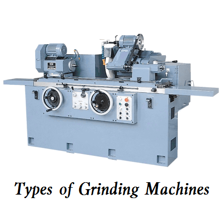
Surface grinding machines are one of the most commonly used grinding machine types; their construction and motion are similar to milling machines. A surface grinding machine operates by utilizing a rotating grinding wheel to smooth the surface of a workpiece, which is typically mounted on a magnetic bed. To begin, the operator places the workpiece on the bed and secures it using a locking mechanism. The machine features multiple adjustment wheels that allow for precise movement of the workpiece both horizontally (left and right) and vertically (up and down). The grinding wheel, which rotates in a specific direction, is lowered to make contact with the workpiece. As the wheel grinds the surface, the operator can move the bed back and forth to achieve an even finish. The grinding wheel of surface grinders is softer than that used in bench grinders, allowing it to wear evenly and maintain flatness.
Surface Grinder vs Milling Machine: What Are the Differences?
| Feature | Surface Grinder | Milling Machine |
|---|---|---|
| Working Principle | High-speed grinding wheel removes material via friction; worktable moves beneath wheel. | Rotating cutter shapes workpiece; cuts intermittently to produce chips. |
| Cutting Tools | Grinding wheels (silicon carbide/aluminum oxide); die/angle grinders for specific tasks. | Milling cutters (end mills, face mills, slotting cutters) are tailored for diverse operations. |
| Material Removal Rate | Low (ideal for finishing, tight tolerances, delicate surfaces). | High (fast material removal for rough machining of metallic parts). |
| Cut Features | Continuous cuts; stable action with minimal interruptions. | Interrupted cuts may cause vibrations affecting surface quality. |
| Heat Generation | High heat from friction; coolants are mandatory to prevent damage. | Less heat is generated; dry machining is possible for some applications. |
| Accuracy | Superior precision and tight tolerances for small/flat surfaces. | Good precision but less fine-tuning for intricate details. |
| Applications | Precision grinding of flat surfaces, grooves, and slots in toolmaking. | Complex shapes in metals, wood, and plastics (gears, molds, engine parts). |
| Draft Sensitivity | No draft impact; wheel covers full surface area. | Requires draft awareness for casting depths and clamping. |
| Coolant Use | Coolants are essential for abrasive machining and chip removal. | Optional for softer materials; fluids are needed for high-speed/hard materials. |
| Entry/Exit Angles | Full/line contact; no critical entry/exit angles. | Gradual entry/exit required to avoid tool damage. |
| Clamping | Magnetic chucks handle most iron castings; minimal deflection risk. | Secure clamping is critical for malleable/nodular iron castings. |
| Vibration | Less prone to chatter on rigid setups with light feeds. | Chatter risk in thin-walled castings may damage tools. |
Types of Surface Grinders
According to the different structures and grinding wheel configurations, surface grinding machines can be categorized into horizontal spindle (peripheral) and vertical spindle (wheel-face) types. There are also single and double-disc surface grinding machines.
1. Horizontal Spindle and Reciprocating Table Surface Grinder
The spindle is horizontally mounted, and the grinding wheel makes contact with the workpiece through its periphery. The worktable reciprocates, and the wheelhead moves vertically to perform grinding. This type of machine is suitable for high-precision grinding of smooth or open surfaces, porous or deep surfaces, such as pistons, pins, connecting rods, and bearing rings. It excels in precision jobs requiring tapered edges or angles and can accommodate materials of various sizes.
2. Horizontal Spindle and Rotary Table Surface Grinder
The worktable rotates instead of reciprocating. The spindle is horizontally arranged, and the grinding wheel’s periphery contacts the workpiece. As the workpiece rotates, the grinding wheel removes uneven bumps. This machine is highly regarded in industries like aerospace and automotive for its suitability for large components and ability to achieve extremely fine finishes.
3. Vertical Spindle and Reciprocating Table Surface Grinder
The spindle is vertically mounted, and the grinding wheel’s end face contacts the workpiece. The reciprocating worktable and the vertical movement of the wheelhead perform the grinding. This type of machine is effective for finishing and rapid material removal. It is suitable for grinding gears, plates, stators, rotors, inner rings, inner plates, stops, spacers, etc., with high accuracy.
4. Vertical Spindle and Rotary Table Surface Grinder
The spindle is vertically mounted, and the wheelhead moves vertically. The worktable rotates, and the grinding wheel’s end face contacts the workpiece. It is ideal for grinding large, circular components and allows for precise grinding of component sizes.
5. Single-disc Grinder
Equipped with a single abrasive wheel, it has a relatively large contact area, enabling faster and more efficient material removal. It is primarily used for deburring, leveling uneven components, and grinding large workpieces in the aerospace and automotive industries.
6. Double-disc Grinder
Features two grinding wheels arranged to grind in opposite directions. The workpiece is sandwiched between the two abrasive wheels, allowing both sides to be ground simultaneously. It is suitable for grinding thin workpieces and can improve production efficiency.
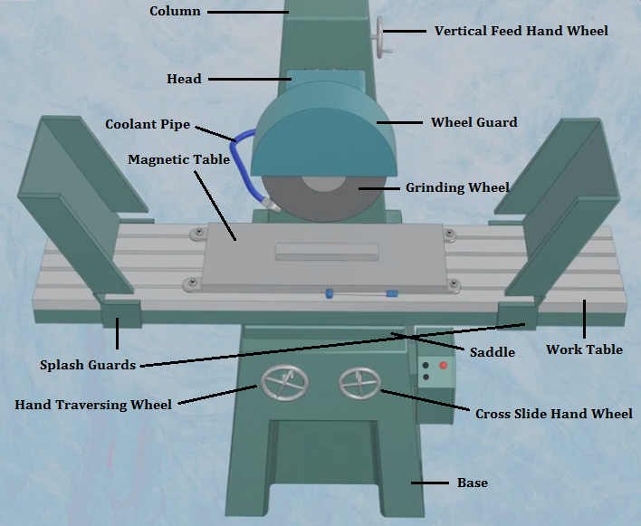
Main Parts of Surface Grinding Machines
- Grinding Wheel: The primary cutting tool that removes material from the workpiece, made of abrasive materials.
- Base: The foundation of the machine that supports all components and absorbs vibrations during operation.
- Work Table: The surface where the workpiece is placed for grinding, providing stability and support.
- Saddle: The component that connects the base and the work table, allowing for horizontal movement.
- Hand Traversing Wheel: Used to move the work table longitudinally, facilitating the grinding process over the workpiece.
- Cross Slide Hand Wheel: Allows crosswise movement of the work table, enabling precise positioning of the workpiece relative to the grinding wheel.
- Magnetic Table: A fixture that magnetizes and holds the workpiece securely in place during grinding.
- Splash Guards: Protective barriers that prevent sparks and debris from escaping the grinding area, ensuring safety.
- Column: The vertical structure that houses the driving mechanism and supports the grinding wheel head.
- Head: Holds the grinding wheel and is responsible for vertical movement to adjust the depth of cut.
- Wheel Guard: A safety feature that covers the grinding wheel to prevent accidental contact and protect the operator.
- Vertical Feed Hand Wheel: Used to adjust the vertical position of the grinding wheel head, controlling the depth of cut.
- Coolant Pipe: Delivers coolant to the grinding area to reduce heat buildup and improve the grinding process efficiency.
Surface Grinding Machine Diagram
Surface Grinding Process & Steps
1. Workpiece Clamping
Secure the workpiece onto the work table of the surface grinding machine. For magnetic workpieces, a magnetic chuck is typically used. For non-magnetic workpieces, mechanical clamping devices may be employed. The workpiece must be firmly clamped to prevent movement during grinding, ensuring machining accuracy and safety. The clamping force should be appropriate to avoid deformation of the workpiece.
2. Grinding Wheel Selection
Choose a grinding wheel based on the workpiece material, desired surface finish, and other factors. Common abrasive materials include aluminum oxide, silicon carbide, diamond, and cubic boron nitride. Aluminum oxide wheels are suitable for grinding steels and alloys, silicon carbide wheels are ideal for grinding cast iron and non-ferrous metals, and diamond or cubic boron nitride wheels are used for grinding hard and brittle materials like ceramics and hard alloys. Additionally, factors such as grain size, wheel hardness, and bonding agent must be considered. Finer grain sizes yield better surface finishes, while harder wheels are suited for grinding soft materials. Resin-bonded wheels provide higher grinding efficiency, whereas vitrified-bonded wheels offer better shape retention.
3. Grinding Wheel Dressing
After prolonged use, the grinding wheel may become dull or develop irregular profiles, affecting grinding efficiency and surface quality. Dressing the wheel restores its abrasive properties and geometric shape, ensuring uniform and sharp abrasive grains on the wheel surface, which enhances grinding precision and surface finish. Dressing tools include diamond dressing rolls or diamond cutters. During dressing, the grinding wheel rotates at a low speed, while the dressing tool moves across the wheel surface at a specific speed and depth to remove dull abrasive grains and reshape the wheel profile. Dressing parameters such as depth of cut, feed rate, and speed must be carefully controlled to achieve optimal dressing results.
4. Positioning the Grinding Wheel
Move the grinding wheel to the desired position above the workpiece, ensuring sufficient clearance between the wheel and the workpiece to prevent collisions. At the same time, adjust the height of the grinding wheel to ensure uniform contact with the workpiece surface.
5. Starting the Grinding Wheel
Activate the grinding wheel motor to bring it up to the required rotational speed. Wait for the grinding wheel to reach stable operation before proceeding with feeding to ensure grinding quality and safety.
6. Workpiece Feeding
The grinding machine’s table moves the workpiece beneath the rotating grinding wheel in a reciprocating motion to remove material layer by layer. Depending on the grinding machine type and operational requirements, the table may move linearly or circularly. Feeding can be manual or automatic. The feed rate must be controlled to avoid excessive material removal, which could damage the grinding wheel or workpiece surface.
7. Material Removal and Surface Finishing
As the grinding wheel rotates and the workpiece feeds, the abrasive grains on the wheel surface cut into the workpiece, removing material in the form of fine chips. Gradually, the roughness and unevenness of the workpiece surface are reduced, achieving the desired flatness and surface finish. During grinding, appropriate cutting fluid may be applied to cool the grinding zone, reduce friction, prevent workpiece surface burns, and improve surface quality. Cutting fluids also help flush away grinding debris, preventing clogging of the grinding wheel and maintaining its cutting efficiency.
8. Workpiece Inspection
After grinding, measure and inspect the workpiece’s flatness, parallelism, surface roughness, and other parameters using precision measuring instruments to ensure they meet the design and process requirements. For high-precision workpieces, optical interferometers or other advanced measuring devices may be used for evaluation.
9. Workpiece Cleaning
Remove residual grinding swarf and cutting fluid from the workpiece surface to prevent corrosion or contamination. Cleaning methods include ultrasonic cleaning, chemical cleaning, or compressed air blowing, depending on the workpiece material and surface condition.
10. Grinding Wheel Maintenance
After use, clean the grinding wheel of debris and store it in a dry, well-ventilated environment to prevent moisture and collisions. If the grinding wheel is damaged or severely worn, it should be replaced promptly to ensure grinding quality and safety.
Related Articles:
 What is Grinding Process & How It Works – Different Types of Grinding
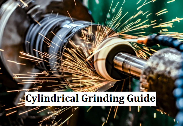 Cylindrical Grinding Definition, Machine, Principle, Process, Diagram, Types, and More
 Spring Material Types (Properties, Grades, Uses) & Best Selection for Your Project
 Clearance Hole Size Chart for Metric and Imperial Fasteners (Bolts, Screws & Studs)
 Different Types of Grinding Machines and How to Use a Grinder – How Does a CNC Grinder Work
 NPS Thread Dimensions Chart (NPSM & NPSL) | What Is Straight Pipe Thread