
Cylindrical grinding is an important manufacturing process widely used in various fields. This guide will cover the cylindrical grinding definition, process, types, grinding machine & wheel (with diagram), components of cylindrical grinders, and wheel specifications.
What Is Cylindrical Grinding? – Cylindrical Grinding Definition
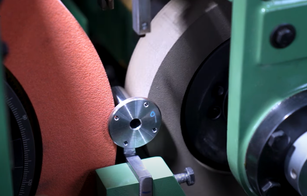
Cylindrical grinding is a type of abrasive machining (cutting) process that uses the grinding wheel to remove materials from the surfaces of workpieces and create cylindrical, conical, or stepped external/internal cylindrical surfaces. The workpiece generally has a central axis of rotation. The sharp abrasive grains on the wheel act as cutting lips to remove tiny chips from the workpiece.
This process applies not only to simple cylindrical shapes but also to more complex geometries such as ellipses, cams, and crankshafts. During cylindrical grinding, the workpiece rotates in the center or in the chuck. At the same time, the grinding wheel moves longitudinally along the length of the workpiece to gradually grind the piece. The grinding operation can target both internal and external surfaces, with external cylindrical grinding being the most prevalent. Internal cylindrical grinding focuses on the inner surfaces of workpieces, using a smaller grinding wheel for tasks like refining bearing inner diameters.
Cylindrical grinding is widely used in industries such as automotive, aerospace, and manufacturing to produce components requiring tight tolerances and smooth finishes, particularly for metals, alloys, and hard materials that are difficult to machine via conventional methods.
Cylindrical Grinding Process
The cylindrical grinding process involves multiple parts of the machine working simultaneously or in sequence, which requires the worker to operate it properly.
1. Workpiece Setup
The workpiece is mounted between centers or clamped in a chuck. Center mounting is typically used for workpieces with high precision requirements. The two centers, headstock and tailstock, hold the workpiece and ensure its rotational stability. Chuck mounting can be employed for shorter or less precise workpieces. The stability of the workpiece setup is critical, as even slight deflection can lead to significant irregularities and defects.
2. Grinding Wheel Setup
Select an appropriate abrasive type for the grinding wheel based on the workpiece material and machining requirements, such as aluminum oxide or silicon carbide. The grinding wheel is then customized, which involves cutting its surface to expose sharp abrasive grains for efficient material removal. Additionally, the grinding wheel must be dressed to achieve the correct shape and surface texture, removing embedded materials and refreshing the wheel to enhance its cutting efficiency.
3. Positioning and Alignment
Adjust the position of the grinding wheel relative to the workpiece to ensure the correct angle and height. Operators also need to set parameters such as rotational speed, cutting depth, and feed rate. The rotational speed of the grinding wheel is generally much higher than that of the workpiece. The table supporting the workpiece can traverse at various feeds to ensure the entire length of the workpiece passes in front of the grinding wheel.
4. Grinding
Rough Grinding: A coarser grinding wheel surface is used to rapidly remove excess material from the workpiece, achieving approximate dimensions. During rough grinding, the depth of cut is relatively large, the feed rate is fast, and the focus is on removing material efficiently. However, the surface roughness is relatively high.
5. Finishing Grinding
A finer grit grinding wheel is employed to achieve the final surface finish and dimensional tolerances. In this stage, the depth of cut and feed rate are reduced to improve surface quality and dimensional accuracy. The grinding wheel gradually moves along the length of the workpiece, removing material and shaping it to the desired specifications.
6. Cooling and Lubrication
During grinding, coolant is applied to reduce heat generation, minimize thermal expansion of the workpiece and grinding wheel, extend the life of the grinding wheel, and achieve a smoother surface finish while preventing overheating of the workpiece. Common coolants include water-based solutions and oil-based fluids. Proper lubrication and cooling are essential to ensure machining quality and efficiency.
7. Measurement and Inspection
After grinding, precision measuring tools such as micrometers, dial indicators, coordinate measuring machines (CMM), and surface roughness testers are used to inspect the workpiece’s dimensions, surface finish (Ra value), and tolerances. Measurements are taken at multiple points to confirm whether the workpiece meets the required specifications. If deviations are found, corrective grinding or other measures are taken.
8. Wheel Maintenance
After completing a grinding cycle, the grinding wheel may become worn or loaded with debris. Regular dressing and tuning are necessary to restore its shape and cutting performance. Dressing involves using a diamond dresser to remove a layer of the grinding wheel’s surface, exposing fresh abrasive grains. Truing ensures the grinding wheel’s roundness and parallelism with the workpiece.
In addition to the above stages, operators need to continuously monitor the grinding process, adjusting parameters such as speed, feed rate, and depth of cut in real time to optimize machining results and avoid issues like vibration or burning.
Types of Cylindrical Grinding
There are different types of cylindrical grinding processes, while OD and ID grinding are the most common ones.
1. Outside Diameter (OD) Grinding
OD grinding, also known as external cylindrical grinding, is used to machine the outer surfaces of cylindrical workpieces. The workpiece is mounted between centers or in a chuck and rotates while the grinding wheel contacts its outer surface. This method is commonly used for machining shafts, rods, and other cylindrical components. OD grinding offers advantages such as high precision, smooth surface finish, and versatility across various materials. It is suitable for mass production and can produce components with tight tolerances and excellent surface quality.
2. Inside Diameter (ID) Grinding
ID grinding, or internal cylindrical grinding, is used to grind the internal surfaces of cylindrical workpieces, such as the inner diameters of bearings or cylindrical bores. The grinding wheel used in ID grinding is smaller and operates inside the workpiece. The process involves three main methods: traverse grinding, plunge grinding, and grinding the ends of blind holes. In traverse grinding, the wheel spindle reciprocates along the length of the bore while the component is held by its outer diameter. In plunge grinding, the component is held externally, and the wheel head feeds the wheel into the component at a right angle to the component’s axis. ID grinding is used to produce precision internal surfaces, such as those required for hydraulic components, engine parts, and other applications demanding high accuracy and surface quality. It is characterized by its ability to achieve high precision and fine surface finishes, but requires higher technical expertise and more complex equipment.
3. Creep Feed Grinding
Creep feed grinding is a high-efficiency grinding process involving slow feed rates and deep cuts. The grinding wheel feeds slowly into the workpiece at a relatively low speed while removing a large amount of material in a single pass. This technique is particularly effective for machining hard materials or complex geometries, such as those found in aerospace components and high-precision molds. Creep feed cylindrical grinding can significantly reduce machining time and improve production efficiency, but places higher demands on the grinding wheel and machine tool. It requires a high-power grinding machine and a grinding wheel with excellent wear resistance and heat dissipation properties. Additionally, coolant application and chip removal must be carefully controlled to ensure machining quality.
4. Centerless Cylindrical Grinding
Unlike center-type grinding, centerless cylindrical grinding does not require a spindle or fixture to hold the workpiece. Instead, the workpiece is supported by a work rest blade and rotated by a regulating wheel while being ground by a grinding wheel. The workpiece is positioned between the regulating wheel and the grinding wheel, with the grinding wheel responsible for material removal and the regulating wheel controlling the workpiece’s rotation speed and feed rate. Centerless grinding is ideal for high-volume production of small cylindrical parts, such as pins, rods, and tubes. It offers advantages like high efficiency, excellent dimensional accuracy, and good surface finish. It is especially suitable for machining workpieces with small diameters and high length-to-diameter ratios. However, it requires precise adjustment of the machine tool and grinding wheel to ensure stable workpiece positioning and grinding quality.
What Is a Cylindrical Grinding Machine?
A cylindrical grinding machine or cylindrical grinder is the equipment used in the process. There is no limit to the shapes that can be processed by a cylindrical grinder, but the workpiece must have a central axis of rotation. It usually employs an abrasive grinding wheel to remove material from the workpiece, achieving high-precision, round, and concentric shapes. These machines play a crucial role in manufacturing, enabling the shaping and refining of cylindrical workpieces to meet exacting specifications. Whether it’s the production of critical engine components, precision bearings, or intricate shafts, cylindrical grinding machines are indispensable in achieving the tight tolerances and excellent surface finishes required in modern engineering and manufacturing processes. The operation of a cylindrical grinder resembles that of a lathe machine, with the key difference being the use of a grinding wheel instead of stationary cutting tools. Cylindrical grinders are suitable for materials with a central axis of rotation, such as crankshafts.
Cylindrical Grinding Machine Diagram
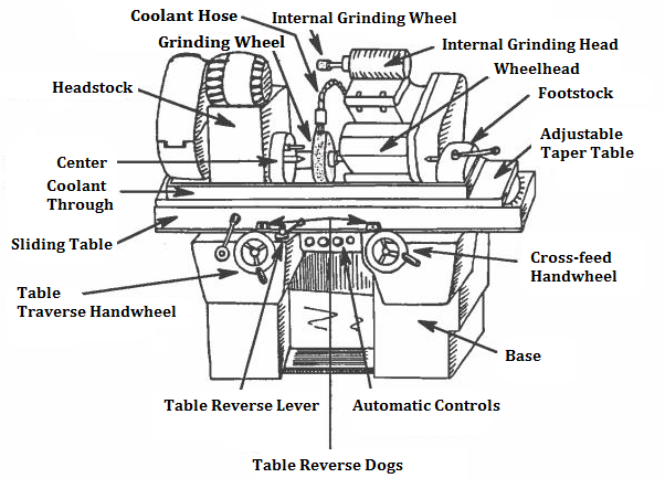
Components of Cylindrical Grinding Machines – Cylindrical Grinder Parts
Cylindrical grinders consist of several key components that work together to enable the precise grinding of cylindrical surfaces. Here is a showcase of each component on the above diagram with its use.
- Coolant hose: A flexible pipe connected to the coolant system, delivering fluid to the grinding zone to cool the workpiece and remove debris.
- Grinding wheel: A rotating abrasive disc mounted on the wheel head, used to precisely remove material from workpieces.
- Wheel head: A movable assembly holds the grinding wheel and allows it to move vertically. This movement is controlled by the cross-feed handwheel or a power source.
- Internal grinding wheel: A smaller abrasive wheel mounted on the internal grinding head, designed for grinding internal surfaces or holes.
- Internal grinding head: A separate assembly supporting the internal grinding wheel, allowing positioning for internal grinding operations.
- Headstock: A stationary fixture on the left side that secures and rotates one end of the workpiece via a center.
- Foot stock: A stationary fixture on the right side that supports the other end of the workpiece via a center, working with the head stock.
- Center: A tapered, pointed tool (on head/foot stocks) that holds the workpiece in place and allows rotational movement.
- Coolant through: A component directs coolant through the grinding wheel to the contact zone for enhanced cooling.
- Adjustable taper table: A sliding platform under the workpiece, adjustable to create tapered surfaces during grinding.
- Sliding table: A movable platform supporting the workpiece, sliding longitudinally for precise positioning during grinding.
- Table traverse hand wheel: A manual control near the operator to move the sliding table back and forth along the machine.
- Cross-feed hand wheel: Adjusts the wheel head’s lateral position across the table to control depth of cut.
- Table reverse lever: Engages to reverse the sliding table’s direction, enabling reciprocating grinding motions.
- Automatic controls: Electronic/hydraulic systems on the control panel for automated machine operation and precision adjustments.
- Base: The heavy-duty foundation supporting all machine components and ensuring stability during operation.
- Table reverse dogs: Mechanisms near the sliding table that trigger directional reversal using the reverse lever.
What Is a Cylindrical Grinding Wheel?
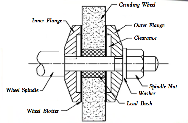
The universal cylindrical grinder is often equipped with two wheels, the larger one for external grinding and the smaller one for internal grinding. A cylindrical grinding wheel is a high-speed abrasive tool designed specifically for cylindrical grinding processes. It consists of sharp, heat-resistant abrasive grains bonded together in a cylindrical shape, with a central hole for mounting on the grinder’s spindle. Its core function is to remove tiny chips from workpiece surfaces to achieve superior surface finish, tight dimensional tolerances, and shape accuracy.
Grinding Wheel Diagram
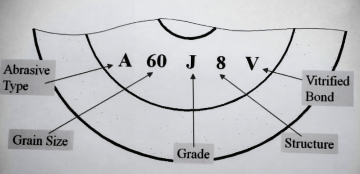
Grinding Wheel Specification & Markings Explained
How to read a grinding wheel specification? The grinding wheel marking system consists of five core components: abrasive type, grain size, grade, structure, and bond type. These markings determine the wheel’s performance, compatibility with workpieces, and grinding results.
1. Abrasive Type
The first capital letter indicates the abrasive type, which refers to the material of the tiny cutting particles (abrasive grains) in the grinding wheel, which is the core factor determining the wheel’s ability to grind different workpieces. The abrasive material must be harder than the workpiece material; otherwise, it can’t cut the workpiece, and must be resistant to the impact of high-speed rotation, and able to withstand the extreme heat generated during grinding. Aluminum oxide is the most common abrasive material for grinding wheels, accounting for 70%-75% of all abrasives, ideal for grinding high-speed steel and other common ferrous metals. It can’t grind harder materials like carbide.
Common Types:
- A (Regular aluminum oxide)
- WA (White aluminum oxide)
- SD (Synthetic diamond)
- ASD (Synthetic diamond, metal coating)
FA (Semi-friable aluminum oxide) - PA (Pink aluminum oxide)
- SA/HA (Single crystal aluminum oxide)
- AZ (Zirconium oxide)
- C (Black silicon carbide)
- GC (Green silicon carbide)
2. Grain Size
Grain size (the first number) describes the size of the individual abrasive grains in the wheel, directly affecting the material removal rate and the surface finish of the workpiece. Coarse grains are like large rocks, medium grains like smaller stones, and fine/ultra-fine grains like tiny sand particles. Coarse-grain sizes have a faster material removal rate but leave a rougher surface finish; finer grains produce a smoother surface finish but work more slowly.
- Coarse grains (10-20)
- Medium grains (30-60)
- Fine grains (70-120)
- Very fine grains (220-400)
3. Grade
The second letter means the grade, which refers to the strength of the bond that holds the abrasive grains together. It determines how easily worn grains fall off the wheel, which is closely related to the wheel’s self-sharpening ability. There is a grade scale that uses 26 letters to represent different strengths.
- Soft grade: A to H (weak bond strength). Worn grains fall off quickly, exposing new, sharp grains. It is suitable for grinding hard materials (since grains dull fast on hard workpieces and need to be replaced promptly).
- Medium grade: I to S. The most widely used grade for daily grinding work, balancing grain retention and self-sharpening.
- Hard grade: T to Z (strong bond strength). Grains stay firmly attached. It is ideal for small-area grinding tasks (e.g., sharpening knives, blades) where the wheel needs to maintain its shape.
4. Structure
Structure (the second number) describes the density of the abrasive grains in the wheel, i.e., how tightly the grains are packed together. It is usually numbered from 1 to 15, where 1 means the densest and 15 means the most open.
- Dense structure (small number): Grains are closely packed. It is suitable for finishing and precision grinding, as the tight grain arrangement ensures a smooth workpiece surface and precise shaping.
- Open structure (large number): Grains are loosely packed, leaving more gaps between them. These gaps allow grinding chips to escape easily and facilitate coolant flow (if used). It is suitable for rough grinding or grinding tasks that generate a lot of chips.
5. Bond Type
Bond type refers to the material used to bond abrasive grains into the wheel shape, and vitrified bond is the most common one, it made of inorganic materials and processed in a furnace. It has high hardness, good brittleness, and strong shape retention, so this bond is suitable for precision grinding tasks that require a stable wheel shape.
- V (Vitrified)
- B (Resinoid)
- R (Rubber)
- O (MgO)
- E (Epoxy)
- M (Metal)
- EP (Electroplated)
Related Articles:
 Centerless Grinding Definition, Process, Types, Machine, Diagram, Angle, Different with Centered Grinding
 What is Grinding Process & How It Works – Different Types of Grinding
 ABS vs PLA vs PETG vs TPU vs ASA vs PBT vs Nylon Filament, What is the Difference?
 Spring Material Types (Properties, Grades, Uses) & Best Selection for Your Project
 Guide to Surface Grinding Machines: Types, Parts, Diagram, Comparison with Mills and More
 S30V vs S90V vs S110V Steel: Composition, Hardness, Properties, Equivalent, Price Differences