
A spur gear is the most common type of mechanical gear, with a simple design. What is the profile of a spur gear, and how does it work? Here, let’s learn about spur gear definition, functions, applications, manufacturing, types, tooth profile, module, terminology, calculation formulas, dimensions chart & spur gear vs helical gear.
What Is a Spur Gear?
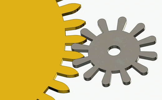
The spur gear is a classic gear type that consists of a cylinder or disk with straight, radially protruding teeth, which are parallel to the central rotating axis. The teeth of a spur gear can be located on the outside or inside of the cylinder. An external gear can mesh with another external gear or an internal gear. An internal gear can only mesh with one external gear. Spur gears are widely recognized for their uncomplicated shape and ease of manufacture. They can vary slightly in hub shape or thickness, but these differences do not affect the gear’s basic face or tooth design.
The most notable feature of a spur gear is its straight teeth, which mesh smoothly with the teeth of another spur gear. This design ensures efficient and reliable power transmission between parallel shafts. Since spur gears only work with parallel shafts, they do not generate any axial thrust during operation. The teeth profiles are usually involute curves, which help maintain a constant speed ratio as the gears rotate. Spur gears are commonly made from materials like steel, brass, bronze, or plastic, and can be hardened for enhanced strength and durability.
What Does a Spur Gear Do?
Functionally, spur gears transmit mechanical motion and power between two parallel shafts. By engaging the straight teeth of one gear with another (with the same pitch and pressure angle), spur gears transfer rotational movement efficiently, controlling speed, torque, and power within the system. Depending on their size and arrangement, spur gears can either increase or decrease the speed of rotation and adjust torque accordingly.
Applications and Uses of Spur Gears
Spur gears are widely used across various industries, including automotive, industrial machinery, and consumer products, because of their simplicity, cost-effectiveness, and reliability. For example, in vehicle transmissions, spur gears help transfer power from the engine to the wheels, enabling movement. Their uniform tooth load distribution leads to smooth operation and a long service life. Additionally, spur gears can be customized with different tooth profiles and sizes to fit specific application needs.
Spur Gear Manufacturing Process & Materials
- Hobbing: This is the most common method for cutting the teeth of external spur gears. A rotating cylindrical cutter called a hob gradually cuts the gear teeth as the gear blank and hob rotate in synchronization. Hobbing creates accurate tooth profiles efficiently.
- Shaping: Gear shaping uses a reciprocating cutter shaped like a gear to cut teeth into the blank. It is especially useful for internal gears or gears with special profiles.
- Planing: Planing involves a rack-shaped cutter that moves linearly against the rotating gear blank to cut the teeth. It is less common but used for specific gear sizes and shapes.
- Broaching: This technique is mainly used for cutting internal gear teeth. A broach tool with progressively larger teeth is pulled or pushed through the gear blank, producing precise internal profiles with smooth finishes.
- Milling: Milling removes excess material from the gear blank to prepare it or to cut gear teeth in low-volume or custom production. CNC milling machines use rotary cutters to shape the gear.
- Drilling: Drilling is used to create central holes or mounting holes in the gear blank.
- Deburring: After cutting, burrs on the gear teeth are removed through mechanical or manual deburring to ensure smooth operation and reduce wear.
Regarding materials, carbon steel is the most commonly used for gear manufacturing because it offers an excellent balance of machinability, wear resistance, strength, and cost-effectiveness. Carbon steel is available in grades such as mild, medium, and high carbon steel, each suitable for different strength and hardness requirements. Depending on the application, other materials like alloy steels, brass, bronze, or plastics may also be used to make spur gears.
Different Types of Spur Gears
The main categories of spur gears are external and internal. There are also other types of spur gears for specific purposes, like anti-backlash, pin hub, rack and pinion, pin hub, split hub, etc.
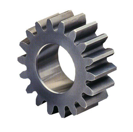
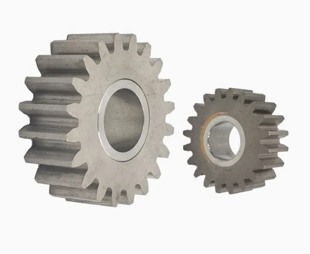
1. External Spur Gear
The external spur gear is the most common and simplest type, with straight teeth cut on the outside surface of a cylindrical gear. These gears mesh with other external spur gears to transmit rotary motion between parallel shafts, with the gears rotating in opposite directions. Their simple design makes them highly efficient and easy to manufacture, which is why they are found in countless gearboxes, motors, timers, and speed reducers across many industries.
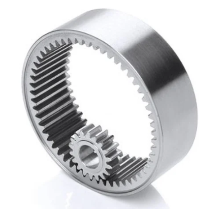
2. Internal Spur Gear
Internal spur gears have their teeth cut on the inner surface of a cylindrical ring. These gears mesh with smaller external gears, causing both gears to rotate in the same direction. This configuration is often used in compact planetary gear systems and specialized drives where space is limited. Internal spur gears provide smooth torque transmission and are common in compact gear reducers and timing devices.
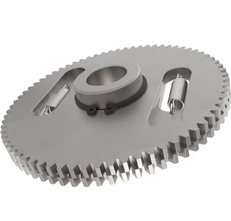
3. Anti-Backlash Spur Gear
Anti-backlash spur gears are designed to minimize the play, or backlash, between the teeth of gears that mesh together. Backlash is generally needed to allow for tooth deflection, thermal expansion, tolerance for tooth profile errors, and proper lubrication. However, in applications requiring high precision, minimal to zero backlash is important. Gear manufacturers have developed anti-backlash gears to meet these demands, adjusting the amount of backlash according to the load requirements. In the case of spur gears, adjustable backlash is achieved by overlapping and slightly shifting two identical gears to control the tooth thickness. These gears are commonly used and are a cost-effective way to reduce inaccuracies in low-torque gear trains.
Anti-backlash spur gears typically consist of two spur gears mounted side by side on an axle, linked by springs. The springs pull the gears against each other, creating a “pinching” effect on the mating gear. This pinching motion compensates for backlash, significantly reducing it upon installation. The precision of anti-backlash gear design makes them suitable for industries such as aerospace, robotics, and high-precision machinery. For example, high-precision telescopes utilize anti-backlash gears to ensure accuracy by eliminating gear play that could distort positioning.
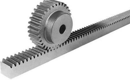
4. Spur Gear Rack and Pinion
Rack and pinion systems combine a cylindrical spur gear (pinion) with a linear toothed rack to convert rotary motion into linear motion or vice versa. This setup is very useful in steering systems, CNC machines, and mechanical actuators, offering precise linear positioning and improved power transmission efficiency. Rack and pinion drives are used in automotive steering, robotics, elevators, and industrial automation.
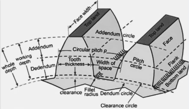
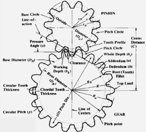
Spur Gear Tooth Profile & Terminology Calculation Formula
Multiple parameters determine the profile or shape of spur gears, including pitch (module/diametral pitch), pressure angle, the number of teeth, and more. When viewed from the side, the tooth faces are straight and aligned parallel to the axis. When it comes to the types of spur gear teeth profiles, they come in involute and cycloidal.
- The involute profile spur gear is the most common and is widely used in modern industry. The pressure angle remains the same when the gear is working. It is favored because its shape ensures smooth and consistent transfer of motion between gears, even if the center distance between the gears changes slightly. The involute curve is generated by unwinding a taut string from a circle, and this shape helps maintain a constant pressure angle during gear rotation. An involute gear is also easier to manufacture than a cycloidal gear.

- The cycloidal profile spur gear is an older design, often found in older or specialized equipment. Its pressure angle is always changing during the operation. The cycloidal tooth shape is based on the path traced by a point on the circumference of a rolling circle, which differs from the involute curve. While cycloidal gears can be effective, they are more sensitive to slight changes in the center distance between gears, and their manufacturing is generally more complex.
Spur Gear Tooth Profile Diagram
| Gear Terminology | Meaning | Calculation Formula | Explanation |
|---|---|---|---|
| Number of Teeth (N) | Total teeth count on the gear | N = P × D | N: Number of teeth P: Diametral pitch D: Pitch diameter |
| Pitch Diameter (D) | Diameter of the pitch circle where the teeth mesh | D = N / DP | D: Pitch diameter N: Number of teeth DP: Diametral pitch |
| Diametral Pitch (DP) | Number of teeth per unit pitch diameter | DP = N / D | DP: Diametral pitch N: Number of teeth D: Pitch diameter |
| Pressure Angle (α) | Angle between tooth face and tangent to pitch circle | Usually 20° (common value) | α: Pressure angle |
| Module (m) | The metric gear size parameter defines tooth size | m = D / N | m: Module D: Pitch diameter (mm) N: Number of teeth |
| Reference Diameter (d) | Diameter used in gear design calculations | Related to module, center distance, pressure angle | d: Reference diameter |
| Face Width / Tooth Height (h) | Width of gear tooth along axis of rotation | h = ha + hf | h: Face width / tooth height ha: Addendum hf: Dedendum |
| Addendum (ha) | Height of tooth above the pitch circle | ha = m | ha: Addendum m: Module |
| Dedendum (hf) | Depth of tooth below the pitch circle | hf = 1.25 × m | hf: Dedendum m: Module |
| Center Distance (C) | Distance between the centers of two meshing gears | C = (N₁ + N₂) / (2 × DP) | C: Center distance N₁: Teeth on driving gear N₂: Teeth on driven gear DP: Diametral pitch |
| Number of Teeth on Driving Gear (N₁) | Teeth count on the driving gear (input gear) | Used in gear ratio and center distance calculations | N₁: Number of teeth on driving gear |
| Number of Teeth on Mating Gear (N₂) | Teeth count on the mating (driven) gear | N₂ = (N₁ × R) / S₂ | N₂: Teeth on mating gear N₁: Teeth on driving gear R: Gear ratio S₂: Desired output speed |
| Gear Ratio (mG) | Ratio of driven gear teeth to driving gear teeth | mG = N₂ / N₁ | mG: Gear ratio N₂: Teeth on driven gear N₁: Teeth on driving gear |
| Input Speed (S₁) | Rotational speed of driving gear (RPM) | S₁ = (S₂ / mG) × (N₂ / N₁) | S₁: Input speed S₂: Output speed mG: Gear ratio N₁, N₂: Teeth on driving and driven gears |
| Desired Output Speed (S₂) | Rotational speed required from the driven gear (RPM) | S₂ = (S₁ × mG) / 60 | S₂: Output speed S₁: Input speed mG: Gear ratio 60: Time conversion factor (seconds to minutes) |
| Outside Diameter (DO) | Total gear diameter, including full tooth height | DO = (N + 2) / DP | DO: Outside diameter N: Number of teeth DP: Diametral pitch |
| Tooth Strength (S) | The capacity of a tooth to withstand applied forces without failure | S = (Y × K × Wt) / FOS | S: Tooth strength Y: Lewis form factor (tooth shape-based) K: Geometry factor Wt: Tangential force on tooth FOS: Factor of safety |
Spur Gear Dimension & Module
The module essentially measures the size of each gear tooth relative to the pitch diameter. The module directly indicates the size and thickness of gear teeth. A larger module means bigger teeth and a larger overall gear, while a smaller module means smaller teeth and a more compact gear. Two gears must have the same module to mesh correctly. If gears have different modules, their teeth will not fit together properly, causing mechanical failure. Standard modules can ensure gears properly engage without interference and allow manufacturers worldwide to produce compatible gears.
The spur gear module (denoted as m) is calculated by dividing the pitch circle diameter (d) of the gear by the number of teeth (z). The pitch circle is an imaginary circle that runs through the gear teeth where the gears effectively mesh. For example, a spur gear with a pitch diameter of 100 mm and 20 teeth will have a module of 5 (100 / 20 = 5 mm). This means each tooth corresponds to a 5 mm segment of the pitch circle diameter.
Spur Gear Size Chart
The actual gear dimensions need to be calculated by the designer based on standard tooth profile parameters, the selected module, and the number of teeth. Below are two spur gear dimension tables for reference in actual production.
1.0 Mod Spur Gear Dimensions Chart
The letters “A” and “B” in Cat.No. indicates the gear type, type A gear with 1 mod has a 25mm width, and the width of type B gear with 1 mod is 15mm.
| Cat. No. | No. Teeth | Pitch Dia. dp | Min Bore d | Max. Bore | Hub ⌀ C | Outside Dia. D | Weight kg |
|---|---|---|---|---|---|---|---|
| S1012B | 12 | 12 | 6 | 6 | 9 | 14 | 0.012 |
| S1013B | 13 | 13 | 6 | 7 | 10 | 15 | 0.016 |
| S1014B | 14 | 14 | 6 | 7 | 11 | 16 | 0.020 |
| S1015B | 15 | 15 | 6 | 8 | 12 | 17 | 0.025 |
| S1016B | 16 | 16 | 6 | 8 | 13 | 18 | 0.030 |
| S1017B | 17 | 17 | 7 | 9 | 14 | 19 | 0.033 |
| S1018B | 18 | 18 | 8 | 10 | 15 | 20 | 0.038 |
| S1019B | 19 | 19 | 8 | 10 | 15 | 21 | 0.045 |
| S1020B | 20 | 20 | 8 | 11 | 16 | 22 | 0.055 |
| S1021B | 21 | 21 | 8 | 11 | 16 | 23 | 0.058 |
| S1022B | 22 | 22 | 8 | 12 | 18 | 24 | 0.060 |
| S1023B | 23 | 23 | 8 | 12 | 18 | 25 | 0.065 |
| S1024B | 24 | 24 | 8 | 13 | 20 | 26 | 0.070 |
| S1025B | 25 | 25 | 8 | 13 | 20 | 27 | 0.075 |
| S1026B | 26 | 26 | 8 | 13 | 20 | 28 | 0.085 |
| S1027B | 27 | 27 | 8 | 13 | 20 | 29 | 0.090 |
| S1028B | 28 | 28 | 8 | 13 | 20 | 30 | 0.095 |
| S1029B | 29 | 29 | 8 | 13 | 20 | 31 | 0.100 |
| S1030B | 30 | 30 | 8 | 13 | 20 | 32 | 0.105 |
| S1031B | 31 | 31 | 10 | 16 | 25 | 33 | 0.110 |
| S1032B | 32 | 32 | 10 | 16 | 25 | 34 | 0.120 |
| S1033B | 33 | 33 | 10 | 16 | 25 | 35 | 0.130 |
| S1034B | 34 | 34 | 10 | 16 | 25 | 36 | 0.135 |
| S1035B | 35 | 35 | 10 | 16 | 25 | 37 | 0.140 |
| S1036B | 36 | 36 | 10 | 16 | 25 | 38 | 0.150 |
| S1037B | 37 | 37 | 10 | 16 | 25 | 39 | 0.155 |
| S1038B | 38 | 38 | 10 | 16 | 25 | 40 | 0.160 |
| S1039B | 39 | 39 | 10 | 16 | 25 | 41 | 0.170 |
| S1040B | 40 | 40 | 10 | 16 | 25 | 42 | 0.180 |
| S1041B | 41 | 41 | 10 | 20 | 30 | 43 | 0.190 |
| S1042B | 42 | 42 | 10 | 20 | 30 | 44 | 0.200 |
| S1043B | 43 | 43 | 10 | 20 | 30 | 45 | 0.210 |
| S1044B | 44 | 44 | 10 | 20 | 30 | 46 | 0.220 |
| S1045B | 45 | 45 | 10 | 20 | 30 | 47 | 0.230 |
| S1046B | 46 | 46 | 10 | 20 | 30 | 48 | 0.240 |
| S1047B | 47 | 47 | 10 | 20 | 30 | 49 | 0.250 |
1.5 Mod Spur Gear Dimensions Chart
The type A gear with 1.5 mod has a 30mm width, and the width of the type B gear with 1.5 mod is 17mm.
| Cat. No. | No. Teeth | Pitch Dia. dp | Min Bore d | Max. Bore | Hub ⌀ C | Outside Dia. D | Weight kg |
|---|---|---|---|---|---|---|---|
| S1512B | 12 | 18.0 | 8 | 9 | 14 | 21.0 | 0.03 |
| S1513B | 13 | 19.5 | 8 | 9 | 14 | 22.5 | 0.04 |
| S1514B | 14 | 21.0 | 8 | 12 | 18 | 24.0 | 0.06 |
| S1515B | 15 | 22.5 | 8 | 12 | 18 | 25.5 | 0.07 |
| S1516B | 16 | 24.0 | 8 | 13 | 20 | 27.0 | 0.08 |
| S1517B | 17 | 25.5 | 8 | 13 | 20 | 28.5 | 0.09 |
| S1518B | 18 | 27.0 | 8 | 13 | 20 | 30.0 | 0.10 |
| S1519B | 19 | 28.5 | 8 | 20 | 25 | 31.5 | 0.11 |
| S1520B | 20 | 30.0 | 8 | 16 | 25 | 33.0 | 0.13 |
| S1521B | 21 | 31.5 | 10 | 16 | 25 | 34.5 | 0.14 |
| S1522B | 22 | 33.0 | 10 | 16 | 25 | 36.0 | 0.15 |
| S1523B | 23 | 34.5 | 10 | 16 | 25 | 37.5 | 0.17 |
| S1524B | 24 | 36.0 | 10 | 16 | 25 | 39.0 | 0.18 |
| S1525B | 25 | 37.5 | 10 | 16 | 25 | 40.5 | 0.19 |
| S1526B | 26 | 39.0 | 12 | 20 | 30 | 42.0 | 0.20 |
| S1527B | 27 | 40.5 | 12 | 20 | 30 | 43.5 | 0.21 |
| S1528B | 28 | 42.0 | 12 | 20 | 30 | 45.0 | 0.22 |
| S1529B | 29 | 43.5 | 12 | 20 | 30 | 46.5 | 0.23 |
| S1530B | 30 | 45.0 | 12 | 20 | 30 | 48.0 | 0.25 |
| S1531B | 31 | 46.5 | 12 | 24 | 35 | 49.5 | 0.27 |
| S1532B | 32 | 48.0 | 12 | 24 | 35 | 51.0 | 0.28 |
| S1533B | 33 | 49.5 | 12 | 24 | 35 | 52.5 | 0.30 |
| S1534B | 34 | 51.0 | 12 | 24 | 35 | 54.0 | 0.32 |
| S1535B | 35 | 52.5 | 12 | 24 | 35 | 55.5 | 0.34 |
| S1536B | 36 | 54.0 | 12 | 24 | 35 | 57.0 | 0.36 |
| S1537B | 37 | 55.5 | 12 | 27 | 40 | 58.5 | 0.38 |
| S1538B | 38 | 57.0 | 12 | 27 | 40 | 60.0 | 0.40 |
| S1539B | 39 | 58.5 | 12 | 27 | 40 | 61.5 | 0.42 |
| S1540B | 40 | 60.0 | 12 | 27 | 40 | 63.0 | 0.45 |
| S1541B | 41 | 61.5 | 14 | 34 | 50 | 64.5 | 0.52 |
| S1542B | 42 | 63.0 | 14 | 34 | 50 | 66.0 | 0.55 |
| S1543B | 43 | 64.5 | 14 | 34 | 50 | 67.5 | 0.57 |
| S1544B | 44 | 66.0 | 14 | 34 | 50 | 69.0 | 0.60 |
| S1545B | 45 | 67.5 | 14 | 34 | 50 | 70.5 | 0.62 |
| S1546B | 46 | 69.0 | 14 | 34 | 50 | 72.0 | 0.65 |
| S1547B | 47 | 70.5 | 14 | 34 | 50 | 73.5 | 0.68 |
| S1548B | 48 | 72.0 | 14 | 34 | 50 | 75.0 | 0.70 |
| S1549B | 49 | 73.5 | 14 | 34 | 50 | 76.5 | 0.72 |
| S1550B | 50 | 75.0 | 14 | 34 | 50 | 78.0 | 0.75 |
| S1551B | 51 | 76.5 | 15 | 40 | 60 | 79.5 | 0.86 |
| S1552B | 52 | 78.0 | 15 | 40 | 60 | 81.0 | 0.87 |
| S1553B | 53 | 79.5 | 15 | 40 | 60 | 82.5 | 0.89 |
| S1554B | 54 | 81.0 | 15 | 40 | 60 | 84.0 | 0.91 |
| S1555B | 55 | 82.5 | 15 | 40 | 60 | 85.5 | 0.93 |
| S1556B | 56 | 84.0 | 15 | 40 | 60 | 87.0 | 0.95 |
| S1557B | 57 | 85.5 | 15 | 40 | 60 | 88.5 | 0.97 |
| S1558B | 58 | 87.0 | 15 | 40 | 60 | 90.0 | 1.00 |
| S1559B | 59 | 88.5 | 15 | 40 | 60 | 91.5 | 1.05 |
| S1560B | 60 | 90.0 | 15 | 40 | 60 | 93.0 | 1.10 |
| S1561B | 61 | 91.5 | 20 | 46 | 70 | 94.5 | 1.20 |
| S1562B | 62 | 93.0 | 20 | 46 | 70 | 96.0 | 1.23 |
| S1563B | 63 | 94.5 | 20 | 46 | 70 | 97.5 | 1.25 |
| S1564B | 64 | 96.0 | 20 | 46 | 70 | 99.0 | 1.27 |
| S1565B | 65 | 97.5 | 20 | 46 | 70 | 100.5 | 1.30 |
| S1566B | 66 | 99.0 | 20 | 46 | 70 | 102.0 | 1.35 |
| S1567B | 67 | 100.5 | 20 | 46 | 70 | 103.5 | 1.38 |
| S1568B | 68 | 102.0 | 20 | 46 | 70 | 105.0 | 1.42 |
| S1569B | 69 | 103.5 | 20 | 46 | 70 | 106.5 | 1.45 |
| S1570B | 70 | 105.0 | 20 | 46 | 70 | 108.0 | 1.48 |
| S1572A | 72 | 108.0 | 20 | 65 | – | 111.0 | 1.18 |
| S1575A | 75 | 112.5 | 20 | 68 | – | 115.5 | 1.28 |
| S1576A | 76 | 114.0 | 20 | 68 | – | 117.0 | 1.32 |
| S1580A | 80 | 120.0 | 20 | 72 | – | 123.0 | 1.45 |
| S1585A | 85 | 127.5 | 20 | 80 | – | 130.5 | 1.60 |
| S1590A | 90 | 135.0 | 20 | 85 | – | 138.0 | 1.85 |
| S1595A | 95 | 142.5 | 20 | 90 | – | 145.5 | 2.04 |
| S15100A | 100 | 150.0 | 20 | 95 | – | 153.0 | 2.30 |
| S15110A | 110 | 165.0 | 20 | 105 | – | 168.0 | 2.81 |
| S15114A | 114 | 171.0 | 20 | 107 | – | 174.0 | 3.30 |
| S15120A | 120 | 180.0 | 20 | 115 | – | 183.0 | 3.39 |
| S15127A | 127 | 190.5 | 20 | 120 | – | 193.5 | 3.78 |
Spur Gear vs Helical Gear: What Are the Differences?
Both spur gears and helical gears are commonly found in industrial applications. What are the actual differences between them?
- Tooth Design
Spur gears have straight teeth that are parallel to the axis of rotation, so the teeth will engage all at once along a single line when two gears mesh. In contrast, helical gears feature teeth that are cut at an angle, forming a helix shape around the gear. This angled tooth design enables the teeth to engage gradually from one end to the other. - Contact Pattern
The way teeth make contact differs significantly between the two gear types. Spur gears have a line contact where one pair of teeth meshes at a time, causing sudden impact forces and higher stress on the teeth. Helical gears, however, maintain multiple teeth in contact simultaneously due to their angled teeth. - Axial Thrust
Because spur gear teeth are straight and mesh along a single plane, they do not generate any axial thrust (force along the axis of the shaft). Helical gears produce an axial force as the teeth slide against each other during rotation. This axial thrust requires additional support on the shaft, such as thrust bearings, to prevent unwanted shaft movement and ensure smooth operation. - Noise and Vibration
Spur gears tend to generate more noise and vibration. Helical gears operate much more quietly and smoothly. This makes helical gears preferable in applications where noise reduction is important, such as automotive transmissions. - Load Bearing
Helical gears generally have a higher load-bearing capacity than spur gears. The angled teeth of helical gears create more surface contact area between mating gears, which distributes the load over multiple teeth. This leads to less wear and longer gear life. Spur gears bear the load on fewer teeth, which can lead to higher wear under heavy loads. - Speed Performance
Helical gears can handle higher torque and maintain quieter operation at faster rotational speeds. Spur gears, although capable of high efficiency at moderate speeds, experience increased noise, vibration, and wear when operated at high speeds. - Manufacturing Complexity and Cost
Spur gears are simpler in design and easier to manufacture. This means lower production costs and easier maintenance. Helical gears require more complex manufacturing processes involving precise angled cuts and three-dimensional motion, increasing their cost. - Applications and Shaft Orientation
Spur gears are primarily used for transmitting motion between parallel shafts in simpler, lower-speed applications like clocks, washing machines, and conveyors. Helical gears can be used for parallel shafts as well, but also allow transmission between crossed or non-parallel shafts. This versatility makes helical gears suitable for automotive transmissions, aerospace, power plants, and marine propulsion systems. - Contact Ratio
The contact ratio is a measure of how many teeth are in contact during gear meshing. Spur gears typically have a contact ratio between 1.2 and 1.6, meaning usually only one tooth is fully engaged at a time. Helical gears have a higher contact ratio, often exceeding 2. This higher contact ratio contributes to smoother power transmission and less vibration. - Efficiency
Spur gears provide very high efficiency, especially in simpler, medium-speed applications where minimizing friction and axial forces is key, often reaching efficiencies of 98-99%. Helical gears are slightly less efficient due to sliding and axial thrust, typically ranging from 95% to 98%, but have other advantages that may justify their small efficiency penalty.
Related Articles:
 Sprocket Types & Size Chart (Pitch Diameter, Specs, Uses, Design) | Chain Sprocket Catalogue
 Gear Types, Classification, Functions, Teeth Profile, Nomenclature & Calculation
 Lock Washer Definition, Types, Size Chart, Uses | Split vs Wedge vs Tooth Lock Washer
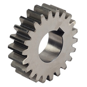 Different Types of Gears and Their Applications | What is Gear & Understanding Common Gears | CNCLATHING
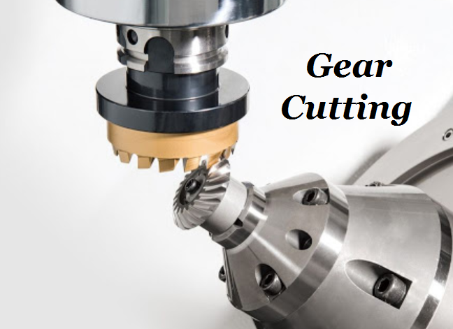 Gear Cutting Process, Materials & Tools | What is Gear Cutting | CNCLATHING
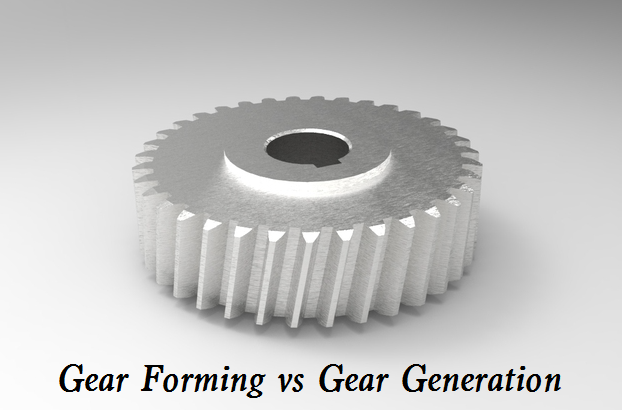 Difference Between Gear Forming and Gear Generating – Gear Forming & Generation Pros and Cons