- Home
- Machining techniques
- CNC Machining Services
- Cooperative supply services
- Designs
- Materials
- Finishing Services
- Shop
- Products
- Guide
- About Us
- Contact Us
2020.10.22
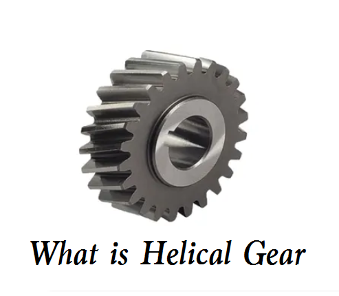 What is Helical Gear – Different Types of Helical Gear and How Do They Work
 Chamfer vs Bevel vs Fillet: Differences In Purpose, Angle, Size, Shape, Machining Tools, Cost, Uses
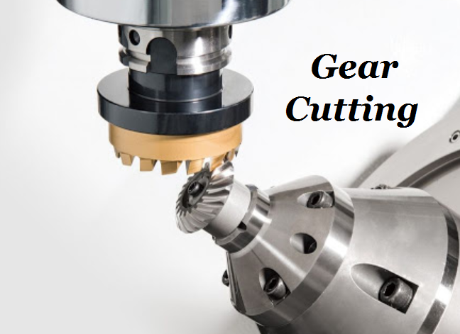 Gear Cutting Process, Materials & Tools | What is Gear Cutting | CNCLATHING
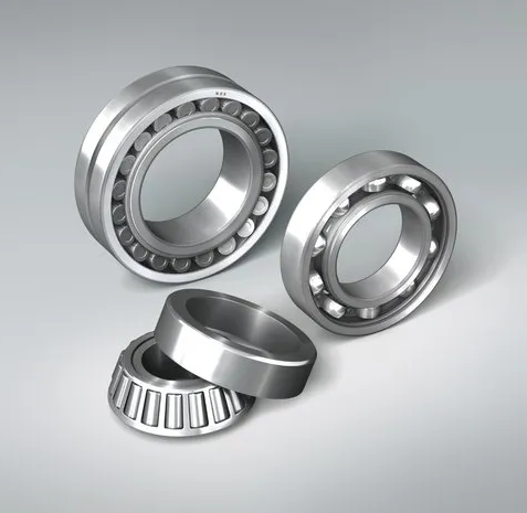 Types of Bearings and Their Applications | Bearing Classification, Definition & Function
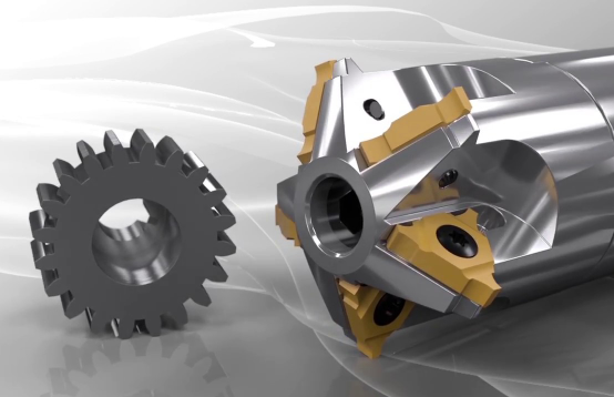 Difference Between Gear Milling and Gear Hobbing | What is Gear Milling | CNCLATHING
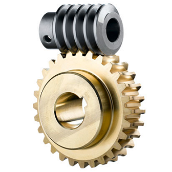
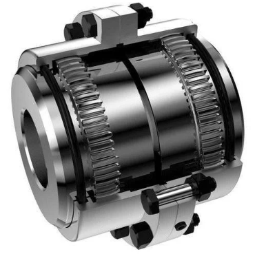 What Is Gear Coupling & How Does It Work – Full & Half Gear Coupling Size Chart
