
Chamfer, bevel, and fillet are the most common edge treatment methods in machining and 3D modeling. They are used to deburr and eliminate sharp edges. However, there are inherent differences between them in terms of definition, design purpose, application, machining techniques, etc. In this CNC machining guide, we are going to tell the difference between them by comprehensively comparing and analyzing to provide references for engineering design and manufacturing.
1. What is Chamfer?
A chamfer in CNC machining is an angled edge cut along the corners of a material. This feature is created through the machining process of grinding, truncating, or deburring the edges or corners of an object at a specific chamfer angle, which forms a sloped surface at a certain inclination to eliminate sharp edges and corners. Chamfers create a straight edge and are extremely useful for preventing chipping and cracking, as sharp edges are eliminated. Since product edges often become weak points prone to breakage, incorporating chamfers not only makes parts more durable but also reduces the risk of injury during handling and assembly. Chamfers are particularly practical on parts that are frequently handled, making them safer and more comfortable to use while also easing assembly and improving long-term durability. Additionally, chamfers can help parts fit together more effectively and can enhance the overall appearance of machine parts.
Chamfer Edge Dimensions (Angle & Length)
Chamfer dimensions are typically specified by two parameters: the distance (length) and the angle. The most common chamfer is cut at 45°, but 30° or 60° angles are used depending on design requirements. In mechanical drawings, a chamfer may be denoted as “C1.0,” which means a 1 mm chamfer at a 45° angle. Sometimes, chamfers are dimensioned with two distances, indicating the lengths of the sides forming the chamfered face. For most engineering parts, the width of a chamfer is narrow, usually between 1 and 2 mm. The actual dimension chosen depends on the thickness of material, safety requirements, and assembly needs. When the angle is not 45°, both the angle and the distance should be clearly indicated on the drawing to avoid ambiguity.
Chamfer Design Purpose & Applications
Chamfers are used to remove sharp edges, making parts safer to handle and reducing the risk of injury. They also make assembly easier by allowing parts to fit together more smoothly and can help prevent damage or chipping at the edges. In addition, chamfering can improve a product’s visual appeal and create a more refined finish, especially after painting or coating. Chamfers are mainly used in engineering machinery, such as machine tool accessories, measuring tools, fixtures, etc., to improve overall strength, machining quality, reduce cutting resistance, prevent scratching operators, etc.
Chamfer Pros & Cons
Pros:
- Reduces risk of injury from sharp edges
- Eases assembly by guiding parts into place
- Minimizes edge chipping or cracking
- Improves aesthetics and finish quality
Cons:
- May require additional machining steps or special tools
- Can add to manufacturing time and cost, especially if multiple or custom angles are needed
Chamfered Edge Machining Process & Tools
Chamfers can be made using a variety of tools such as milling cutters, files, sandpaper, or grinding. For batch production, dedicated chamfering cutters or machines are often used. The choice of tool and method depends on the required angle and size.
Chamfer Cost
Adding chamfers may increase machining complexity, which can lead to higher costs and longer lead times, particularly if non-standard tooling or multiple setups are required.
2. What is Bevel?
A bevel edge is a treatment used to soften an edge by cutting it at an angle, rather than rounding it as with a fillet. The main function of a bevel is to reduce edge wear and to prevent injuries when handling an object. In the context of design and manufacturing, a bevel is the softening of an edge, and it serves a functional purpose by making components safer and more comfortable to use. Bevels are also utilized for preventing chipping and cracking, as sharp edges are often weak points that are prone to breakage. For parts that are frequently handled, bevels contribute to easier assembly and greater durability over time. Essentially, bevels create a straight edge between two surfaces, which can enhance both the safety and longevity of a product.
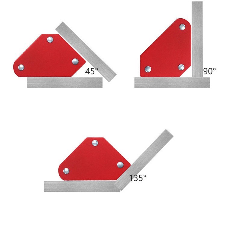
Bevel Edge Dimensions (Angle & Width)
Bevel dimensions are characterized by their angle and width, which are more flexible compared to chamfers. On technical drawings, bevels are often defined by the angle (such as 60°, 75°, etc.) and the width or length of the beveled surface. For example, a bevel might be specified as a 60° angle with a 5 mm width. Bevels often have a much larger width than chamfers, especially for decorative or highly visible surfaces. In some cases, the bevel is defined by two distances (similar to a chamfer), or by a combination of distance and angle. The exact dimensions depend on both the functional and aesthetic requirements of the part, and should be clearly indicated in the design documentation to ensure accurate machining.
Bevel Design Purpose
While eliminating sharp corners, a bevel also has a decorative function. The angle and width of a bevel can be flexibly designed according to the desired decorative effect, generally choosing an angle greater than 45° and a much larger width than a chamfer. The design of a bevel takes aesthetics and customization requirements into account.
Bevel Design Purpose & Applications
Bevels serve both functional and safety purposes. They help soften edges, making parts safer to handle and use, and reduce the risk of edge wear or injury. Bevels are also often used in woodworking, metalworking, and glass-cutting to ease assembly or achieve a specific visual effect. In addition to engineering applications, bevels are more often used in areas that require aesthetic appearance, such as high-end furniture, handicrafts, architectural decoration, etc., to enhance individuality and decorativeness.
Bevel Pros & Cons
Pros:
- Reduces edge wear and risk of injury
- Allows for custom angles and profiles beyond standard chamfers
- Can be used for decorative or functional transitions
Cons:
- May require more complex machining or custom tooling
- Increases manufacturing time and cost if multiple or unusual angles are needed
Bevelled Edge Machining Process
Bevels can be produced using similar tools as chamfers, including bevel mills and grinding wheels. The process depends on the desired angle and finish.
Bevel Cost
The cost of adding bevels depends on the angle and complexity. Non-standard bevels may require custom setups, which can increase machining time and expenses.
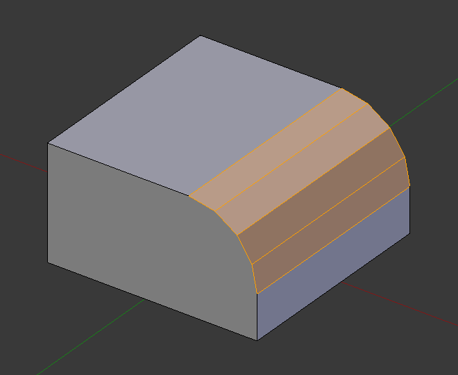
3. What is Fillet?
A fillet refers to the process of rounding off the sharp edges or corners of a part, typically resulting in a smooth, curved transition, so it is also known as the round chamfer. This feature is commonly used on both internal and external edges, but it is most often associated with internal corners. A fillet is a rounded interior or exterior corner or edge incorporated into a part, providing a smooth curve transition rather than a sharp angle. In practical terms, filleting is the art of rounding the sharp edges to make them smooth, which is particularly important for reducing stress concentration in materials, thereby improving the strength and durability of a part. When looking at a model, the fillet tool rounds off edges by applying a curved shape to them, making them appear less sharp and more natural. In addition to aesthetics, fillets are usually used to distribute loads more evenly, reducing the risk of cracks and material fatigue, and they can also help with part assembly by eliminating sharp, potentially dangerous edges.
Fillet Edge Dimensions (Angle & Radius)
Fillet dimensions are defined by the radius of the arc used to round the edge or corner. On technical drawings, this is indicated with an “R” followed by the radius value, such as “R2.0” for a 2 mm radius fillet. Fillet radii can be small (e.g., 0.2–0.3 mm) for fine edge smoothing or much larger for strength and stress reduction in load-bearing components. The choice of fillet radius affects both the appearance and the mechanical performance of the part. In situations requiring high accuracy, the fillet radius should match the drawing precisely, as even small deviations can influence stress concentration and fit. For complex geometries, variable radius fillets may be specified, allowing the radius to change smoothly along the edge.
Fillet Design Purpose & Applications
Fillets are used to reduce stress concentration at corners, which helps improve the strength and durability of parts, especially those subject to loads or repeated stress. They also enhance the appearance of products and make them more comfortable to handle. Fillets are especially important in load-bearing components, as they help distribute loads more evenly and reduce the risk of cracks or material fatigue.
Fillet Pros & Cons
Pros:
- Reduces stress concentration and increases part strength
- Improves durability and fatigue resistance
- Enhances comfort and aesthetics
- Makes cleaning easier due to the absence of sharp corners
Cons:
- Can complicate manufacturing, especially in processes like 3D printing or CNC machining
- May require special tools or multiple passes for larger radii
- Adds to machining time and cost
Filleted Edge Machining Process
Fillets can be created with radius cutters, dedicated fillet tools, or by using filleting features in CAD/CAM software. In manufacturing, multiple passes may be needed for large fillets, and precise control is required to match the specified radius.
Fillet Cost
Adding fillets may increase machining time and may require non-standard tooling, especially for tight radii or complex geometries. This can add to the overall cost and lead time.
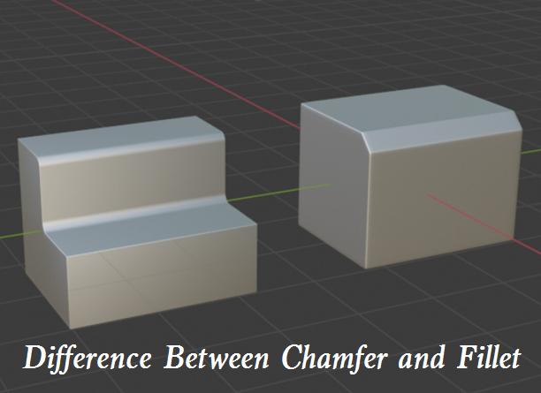
4. Chamfer vs Bevel vs Fillet: What are the Differences Between Them?
After our detailed introduction to chamfering, beveling, and filleting, you should now understand these three common processing edges in engineering. Now let’s use a brief comparison table to help you understand the differences and relationships between them at a glance:
| Aspect | Chamfer | Bevel | Fillet |
|---|---|---|---|
| Definition | Flat, angled cut at the edge or corner, typically 45° | Inclined surface at the edge or corner, angle often >45°, can be wide or decorative | Rounded (curved) transition between two surfaces, usually defined by a radius |
| Shape | Straight, planar surface between two faces | Sloped or curved transition, can be flat or arc-shaped | Smooth, curved arc at the intersection of two surfaces |
| Typical Angle | Usually 45°, but can be 30°, 60°, etc. | Variable, often >45° (e.g., 60°, 75°); more flexible | Not defined by angle, but by radius (R) |
| Width/Size | Narrow, generally 1–2 mm | Can be much wider than a chamfer | Radius typically specified; can be small or large |
| Design Purpose | Improve mechanical strength, reduce stress, ease assembly, deburr | Decorative and functional, softens edge, customizable for aesthetics | Reduce stress concentration, improve strength, create smooth transitions |
| Appearance | Maintains squareness, preserves geometry, industrial look | Emphasizes streamlined or glossy shapes, can alter overall corner | Smooth, rounded appearance |
| Effect on Corners | Maintains original corner angle | Can reduce or eliminate the original corner angle | Rounds off the corner, replacing sharp change with a curve |
| Common Uses | Industrial parts, fixtures, mechanical components, woodworking | Decorative edges, furniture, architectural details, high-end finished parts | Load-bearing parts, plastic/metal housings, areas needing stress relief |
| Machining Method | Simple, high-speed tools, single pass, easy to automate | Multiple passes, complex tool paths, CNC required for accuracy | Special radius tools or CNC, may require multiple passes for large radii |
| Machining Tools | Grinding discs, planers, chamfering cutters | Planers, ball nose tools, CNC machines | Radius cutters, fillet tools, CNC |
| Machining Time & Cost | Low—fast and efficient, suitable for mass production | Higher—more complex, slower, increased tool wear | Moderate—depends on radius size and tool availability |
| Surface Finish | Flat, easier for coating/finishing, but coating adhesion may be lower | Curved, better for coating adhesion, longer-lasting finishes | Excellent for coatings, as curves reduce peeling and cracking |
| Stress Concentration | Minor stress risers may remain | Curves help reduce stress concentration | Greatly reduces stress concentration, improves part durability |
| Ease of Processing | Easy, low skill required, few quality risks | More difficult, higher skill needed, greater risk of errors | Intermediate—depends on radius and process |
| Application Selection | Preferred for strength, cost efficiency, and simplicity | Chosen for aesthetics, customization, and coating requirements | Ideal for stress relief, durability, and organic transitions |
5. When to Use Chamfer, Bevel, or Fillet?
Based on the differences above, the following principles can be summarized for selecting chamfered, bevelled, and filleted edges:
- Use chamfers when you need to remove sharp edges for safety, ease assembly, or improve aesthetics with a simple, flat angled edge. They are especially useful for parts that are handled frequently or require a clean, precise look.
- Use fillets when stress concentration is a concern, such as in load-bearing parts or where fatigue resistance is needed. Fillets are also preferred for comfort and in designs where smooth, organic curves are desired.
- Use bevels for custom-angled transitions that go beyond the standard chamfer, or when a specific visual or functional requirement calls for a non-45° angle.
In manufacturing, the choice may also depend on machining capabilities, cost, and the intended function of the part. For example, in 3D printing, chamfers often produce cleaner results than fillets on top or bottom surfaces, while fillets may work better on side faces.
Related Articles:
 Difference Between A Chamfer and Fillet – When to Use Chamfer and Fillet
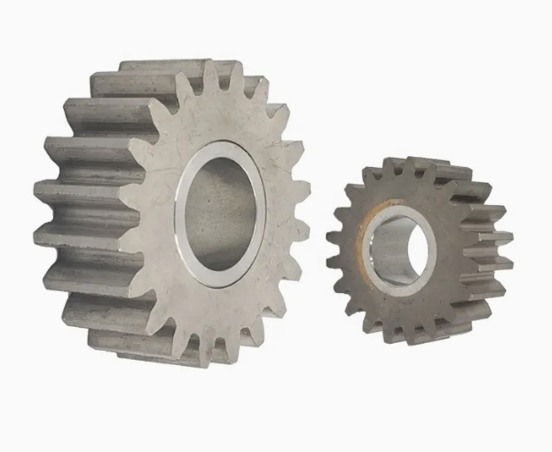 Gear Types, Classification, Functions, Teeth Profile, Nomenclature & Calculation
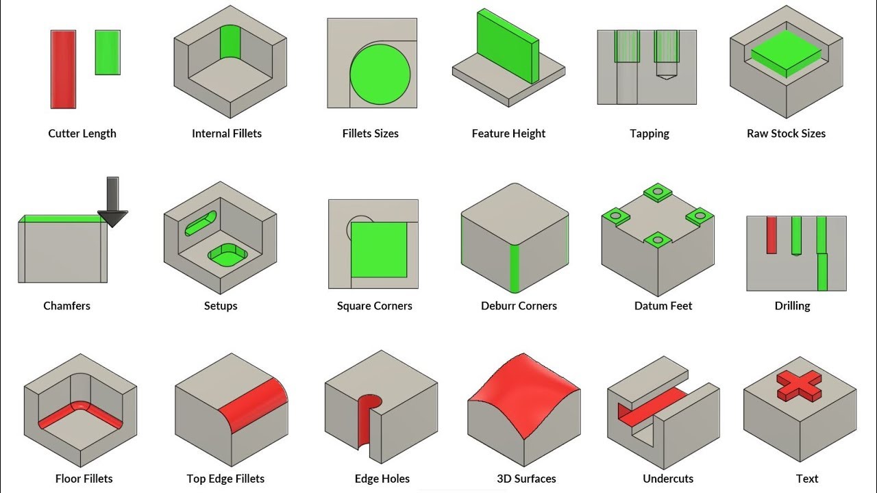 CNC Machine Parts Designing Guide – CNC Machining Design Parts For Fillets, Tapping, Chamfers, Setups, And More
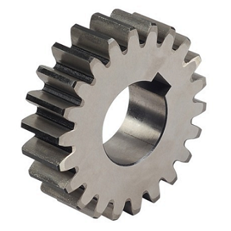 Different Types of Gears and Their Applications | What is Gear & Understanding Common Gears | CNCLATHING
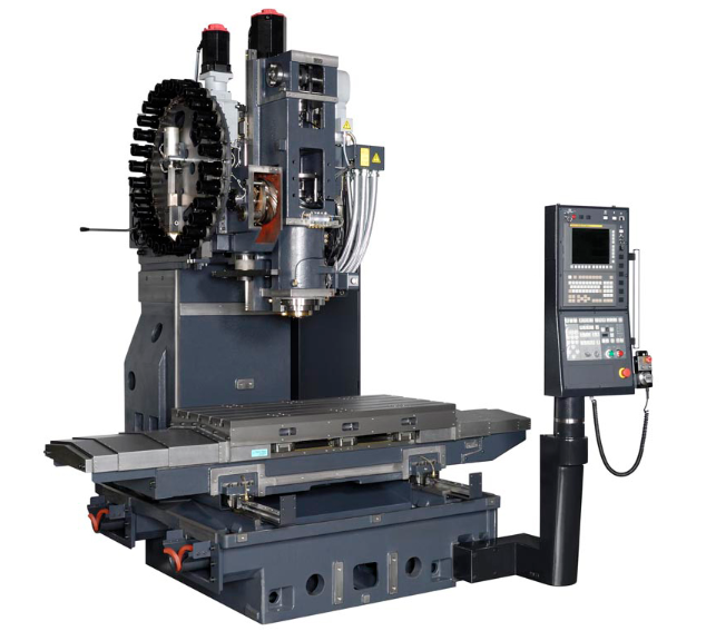 What is CNC Vertical Machining Center – VMC Machine Applications & Difference Between Horizontal Machining Center
 Shaft Key Types, Size Chart, Material Grades, Design Formula & Calculation