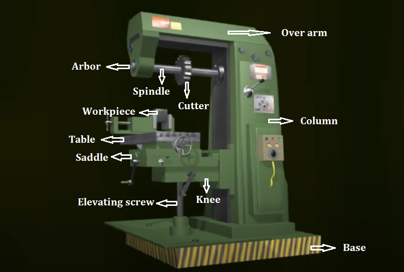
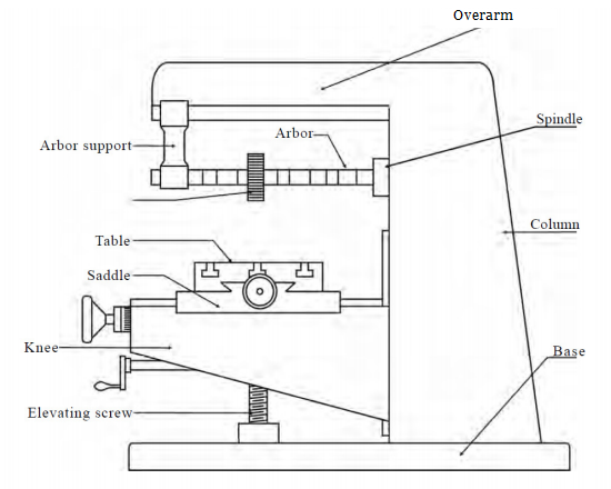
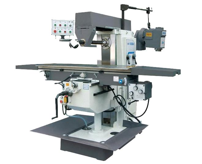
The construction is the basis of learning about using a CNC milling machine. Plain milling is a common type of milling operation. Here we bring the plain milling machine diagram with the machine parts and functions, to help beginners get into the working of milling machine.
1. Base: acts as the foundation of the whole machine, provides support and rigidity, sometimes used as a reservoir for the cutting fluids
2. Column: the main supporting frame mounted vertically on the base, contains all the driving mechanism for the spindle and table feed, as well as guide ways to slide the knee up and down.
3. Knee: a rigid casting mounted on the front face of the column, slide along the guideways up and down by elevating screw, which enables distance adjustment between the cutter and parts, used to support the saddle, table, workpiece, and clamping devices.
4. Saddle: the intermediate part between the knee and table, mounted on the guideway of the knee to support and carry the table, moves transversely.
5. Table: located on guideways in the saddle, with t-slots and accurately finished top surface to hold and clamp the workpiece. It can move in three directions: vertical (up and down), cross (in or out), longitudinal (back and forth).
6. Overarm: mounted on the top of the column, acts as the support for the arbor.
7. Arbor: can be fitted at any location of the overarm, the extension of the machine spindle, to hold and drive the milling cutters.
8. Spindle: located in the upper part of the column, mounted with the milling cutter.
9. Elevating screw: used to move the knee and table up or down automatically or manually
 Column And Knee Type Milling Machine: Definition, Types, Parts, Diagram and Construction | CNCLATHING
 What is A Bed Type Milling Machine | Difference Between Knee Mill and Bed Mill
 Why Choose China CNC Machining and How to Find the Best CNC Machining Manufacturer
 Classification of Milling Machine – Common Types of CNC Milling Machines | CNCLATHING
 Horizontal Milling Machine Basics: Definition, Features, Construction & How Does It Work | CNCLATHING
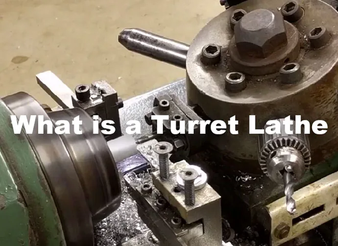 What is a Turret Lathe & How It Works – Turret Lathe vs Engine Lathe & Turret Lathe vs Capstan Lathe
