- Home
- Machining techniques
- CNC Machining Services
- Cooperative supply services
- Designs
- Materials
- Finishing Services
- Shop
- Products
- Guide
- About Us
- Contact Us
2021.4.27
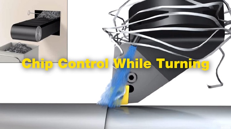
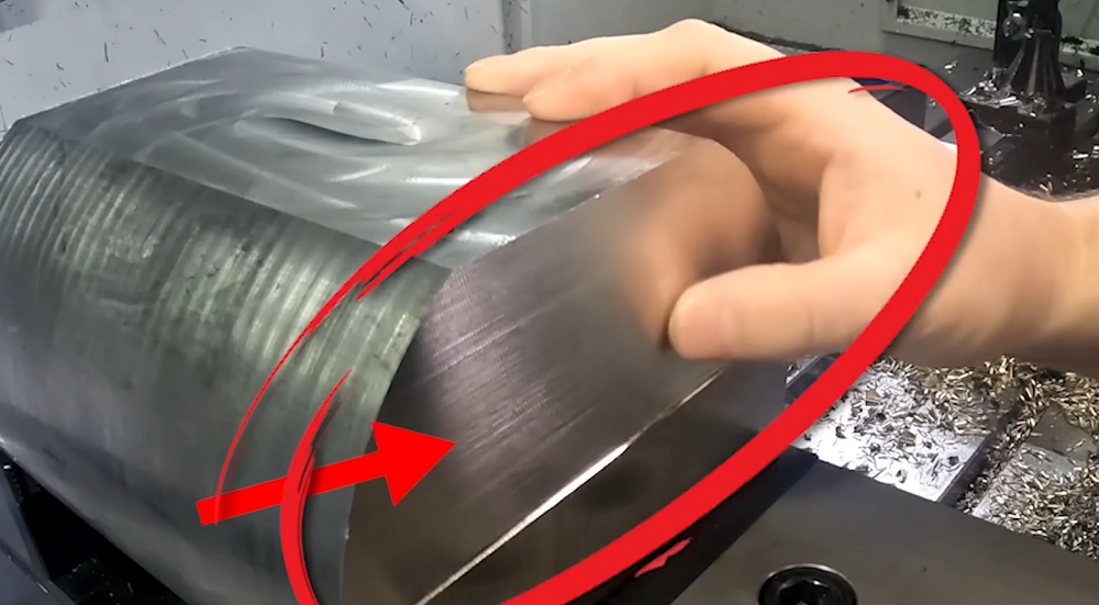
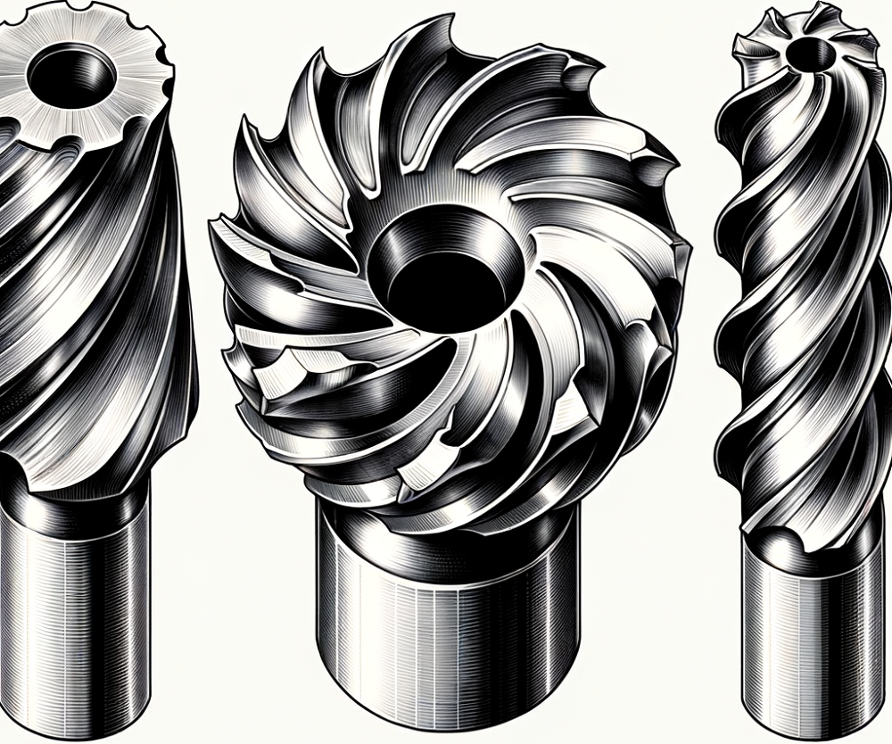
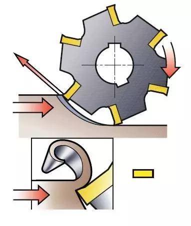
Chip control and chip jamming present major challenges in all turning operations. Poor chip control can lead to reduced workpiece quality, scrap component, wasted material, shorter tool life and machine stoppage. All factors that negatively impact productivity. The insert nose radius, rake angle, chipbreaker form, cutting speed and feed, and coolant flow all should be considered for successful chip control when cutting metal. In this guide, we will explore CNC chip control tips to ensure quality chip control in conventional operations.
 Ball Nose vs Flat End Mill – Ball Nose End Mill Speeds and Feeds
 What is Peck Drilling – Peck Drilling Meaning, Cycle, G Codes, Depth, Speed, Uses & Examples
 How To Reduce & Stop Chatter Vibration in CNC Milling/Turning/Drilling/Grinding Lathe?
 Face Mill vs Shell Mill vs End Mill Cutters: Differences & When To Use Each Milling Cutter?
 Guide to CNC Drilling: Chip Breaking and Removal, Hole Precision Improvement and More | CNCLATHING
 Climb Milling vs. Conventional Milling: Differences in Pros, Process, Surface Finish, Cost & More
