
Engineering drawings often include a small note such as:
GENERAL TOLERANCES: ISO 2768-m
For many engineers, this note defines the default tolerances applied to dimensions that are not individually specified.
The ISO 2768 tolerance standard is widely used in mechanical engineering, CNC machining, sheet metal fabrication, and general manufacturing to simplify drawings and reduce unnecessary tolerance specifications.
In this guide, you will learn:
- What ISO 2768 means
- The ISO 2768-m tolerance class
- The ISO 2768 tolerance chart
- How to read an ISO 2768 drawing example
- Common mistakes and manufacturing considerations
What Does ISO 2768 Mean?
ISO 2768 is an international standard that defines general tolerances for linear, angular, and geometrical dimensions when no specific tolerance is indicated on an engineering drawing.
The standard is widely referenced in mechanical engineering drawings across Europe, Asia, and global manufacturing industries.
ISO 2768 consists of two parts:
- ISO 2768 1 — General tolerances for linear and angular dimensions
- ISO 2768 2 — General geometrical tolerances
Authoritative source: International Organization for Standardization (ISO 2768 1:1989, ISO 2768 2:1989)
ISO 2768-m Meaning
One of the most common notations on engineering drawings is:
ISO 2768-m
The letter m represents the medium tolerance class.
ISO 2768 defines four tolerance classes:
| Class | Meaning |
|---|---|
| f | Fine |
| m | Medium |
| c | Coarse |
| v | Very coarse |
Among them, ISO 2768-m is the most commonly used class in mechanical engineering and CNC machining, because it provides a good balance between manufacturability and cost.
Note: ISO 2768 only applies to dimensions without individually specified tolerances. Dimensions with explicit tolerances always override the standard.
ISO 2768 Tolerance Chart (Linear Dimensions)
The ISO 2768 tolerance chart specifies allowable deviations depending on the nominal dimension size.
Example values for ISO 2768-m:
| Nominal Length (mm) | Tolerance (ISO 2768-m) |
|---|---|
| 0.5 – 3 | ±0.1 |
| 3 – 6 | ±0.1 |
| 6 – 30 | ±0.2 |
| 30 – 120 | ±0.3 |
| 120 – 400 | ±0.5 |
| 400 – 1000 | ±0.8 |
Example:
- Dimension: 25 mm
- General tolerance: ISO 2768-m
- Allowed range: 25 ±0.2 mm
ISO 2768 Drawing Example
Explanation:
m→ general dimensional tolerance (ISO 2768-1)K→ geometrical tolerance class (ISO 2768-2)
Example application:
| Dimension | Tolerance Source |
|---|---|
| 25 mm | ISO 2768-m |
| Ø12 ±0.02 | Explicit tolerance (overrides ISO 2768) |
| 100 mm | ISO 2768-m |
This module allows engineers to visualize how ISO 2768 is applied to real drawings.
When Engineers Should Use ISO 2768
ISO 2768 is commonly used when:
- Most dimensions do not require tight tolerances
- The design allows standard manufacturing deviations
- Engineers want to simplify drawing documentation
Typical applications:
- CNC machining
- Sheet metal fabrication
- Laser cutting
- Welded structures
- General mechanical parts
Critical functional dimensions should always have explicit tolerances.
When ISO 2768 Should Not Be Used
ISO 2768 general tolerances do not apply to:
- Fits (e.g., H7/g6)
- Thread tolerances
- Surface roughness
- Geometric Dimensioning and Tolerancing (GD&T)
- Individually specified tolerances
ISO 2768 in CNC Machining
In real manufacturing environments, ISO 2768-m is the most widely used tolerance class for machined parts.
It balances:
- Manufacturing cost
- Machining capability
- Inspection requirements
| Process | Typical Capability |
|---|---|
| CNC milling | ±0.01–0.02 mm |
| CNC turning | ±0.01–0.03 mm |
| ISO 2768-m | ±0.1–0.8 mm |
This shows that most CNC processes easily meet ISO 2768-m tolerances, but explicit tolerances are still necessary for functional dimensions such as bearing seats or sealing surfaces.
Common Misunderstandings About ISO 2768
- ✅ Misconception: ISO 2768 applies to every dimension
Fact: Only applies to dimensions without specified tolerances - ✅ Misconception: ISO 2768 guarantees manufacturability
Fact: Manufacturing process capabilities still determine achievable tolerances - ✅ Misconception: ISO 2768 replaces GD&T
Fact: GD&T and ISO 2768 serve different purposes; critical features must still be specified explicitly
CNC Machining Services & ISO 2768
For parts requiring tighter tolerances than ISO 2768-m, precision CNC machining services are often required.
Typical CNC capabilities exceed ISO 2768-m tolerances and can achieve ±0.01–0.03 mm depending on material and process.
Learn more about:
FAQ
- Q1: What does ISO 2768-m mean?
- A: ISO 2768-m indicates the medium tolerance class defined in ISO 2768 1 for unspecified dimensions.
- Q2: What is the difference between ISO 2768-m and ISO 2768-f?
- A: ISO 2768-f defines finer tolerances, while ISO 2768-m represents medium tolerance limits.
- Q3: Does ISO 2768 replace GD&T?
- A: No. ISO 2768 only defines general tolerances and does not replace GD&T specifications for functional geometry.
- Q4: Can ISO 2768-m be used for CNC parts?
- A: Yes. It is commonly used for CNC machined parts because it balances precision and cost.
References
- International Organization for Standardization (ISO 2768 1:1989, ISO 2768 2:1989)
- CNCLATHING: ISO 2768 Tolerance Chart PDF
Related Articles:
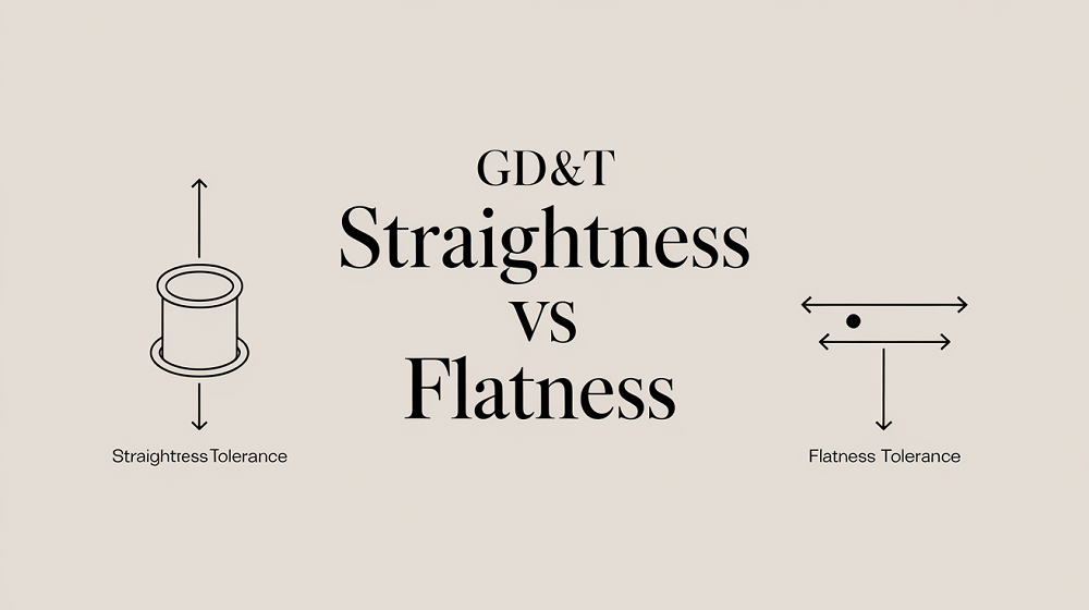 Straightness vs Flatness – Difference Between Flatness and Straightness
 Machining Material Density Chart – Density Unit Conversion Table
 GD&T Profile Tolerance: Basic Knowledge, Types, Symbol, Calculation, Uses
 GD&T MMC: Definition, Formula, Calculation, Bonus Tolerance, Uses, MMC vs LMC
 Threaded Fastener Types, Manufacturing, Inspection, Standards (ISO, ASTM, ANSI)
 Pipe Thread Size Charts in MM/Inches (Dimensions, Types, Standards, Calculation)