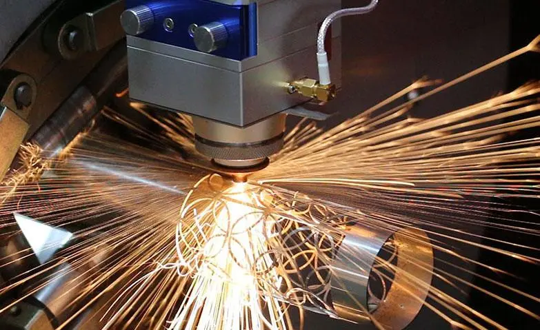
Laser cutting technology has become a widely used material processing method in modern manufacturing. Laser cutting is favored for its high precision, high efficiency, and flexibility. However, tolerance control is critical during laser cutting, because deviations in tolerance can have a significant impact on the quality and performance of the machined product. Now we will present the concept, influencing factors, calculation methods, and optimization of laser cutting tolerance.
What is Laser Cutting Tolerance?
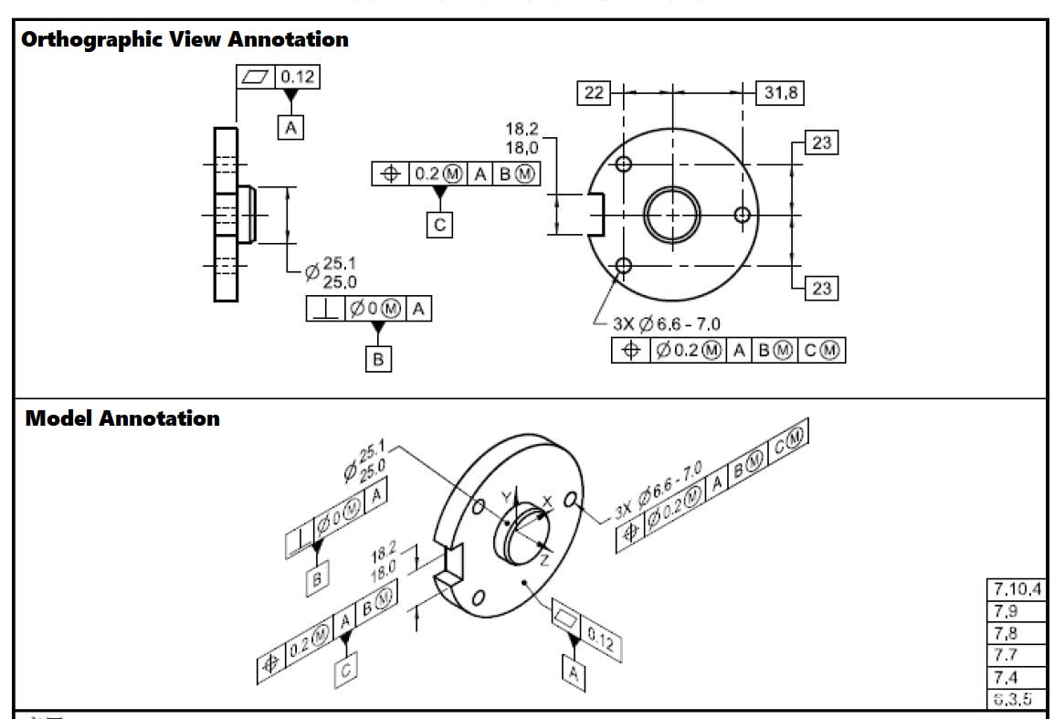
Laser cutting tolerance refers to the maximum allowable difference between the dimensions of the cut part and the design dimensions. It is an important indicator of cutting accuracy and a key factor in determining product quality. The size of laser cutting tolerances determines whether the parts can meet design requirements and fit accurately with other parts.
Laser Cutting Tolerance Standard
What is the standard cutting tolerance for laser? The standard cutting tolerance for laser cutting can vary depending on several factors, including the type of material being cut, the thickness of the material, the precision of the laser cutting machine, and the specific requirements of the project. Tolerances are typically specified as a deviation from the intended design dimensions.
While there is no universally defined standard cutting tolerance for laser cutting that applies to all materials and applications, there are general guidelines and typical tolerances that can be used as a reference. These guidelines provide an indication of the expected range of tolerances for different material thicknesses.
Here is a general guideline for laser cutting tolerances based on material thickness:
Typical Laser Cutting Tolerances
| Material Thickness | Typical Tolerance |
| Up to 0.5 mm | ± 0.05 mm |
| 0.5 mm – 2.0 mm | ± 0.1 mm |
| 2.0 mm – 5.0 mm | ± 0.15 mm |
| 5.0 mm – 10.0 mm | ± 0.2 mm |
| 10.0 mm and above | ± 0.3 mm |
These tolerances serve as a general guide and can vary depending on the specific material, machine capabilities, and project requirements. It’s important to consult with the manufacturer of the laser cutting machine or an experienced professional to determine the appropriate tolerances for the specific materials and applications being used.
Additionally, for precise cuts or when working with specific materials, it is always best to consult with experts and conduct test cuts to determine the optimal cutting parameters and tolerances for the desired results.
Laser Cutting Tolerance Chart
Laser cutting tolerance can vary depending on several factors, including the type of machine used, the nature of the material being cut, the thickness of the material, and the quality of the laser beam. Here is a general guideline for laser cutting tolerances. Please note that actual tolerances can be machine-specific and may also depend on additional factors such as part geometry and the specifics of the cutting process.
Laser Cutting Metal & Plastic Tolerance Chart
The laser cutting tolerances for commonly used metal and plastic materials in machining are shown in the following table:
| Material | Thickness | Tolerance |
| Steel | Up to 1/8″ (3mm) | ±0.005″ (0.13mm) |
| Steel | 1/4″ to 1/2″ (6-12mm) | ±0.01″ (0.25mm) |
| Stainless Steel | Up to 1/8″ (3mm) | ±0.005″ (0.13mm) |
| Stainless Steel | 1/4″ to 1/2″ (6-12mm) | ±0.01″ (0.25mm) |
| Aluminum | Up to 1/8″ (3mm) | ±0.005″ (0.13mm) |
| Aluminum | 1/4″ to 1/2″ (6-12mm) | ±0.01″ (0.25mm) |
| Brass | Up to 1/8″ (3mm) | ±0.005″ (0.13mm) |
| Brass | 1/4″ to 1/2″ (6-12mm) | ±0.01″ (0.25mm) |
| Copper | Up to 1/8″ (3mm) | ±0.005″ (0.13mm) |
| Copper | 1/4″ to 1/2″ (6-12mm) | ±0.01″ (0.25mm) |
| Acrylic | Up to 1/4″ (6mm) | ±0.005″ (0.13mm) |
| Acrylic | 1/4″ to 1/2″ (6-12mm) | ±0.01″ (0.25mm) |
| Polycarbonate | Up to 1/4″ (6mm) | ±0.005″ (0.13mm) |
| Polycarbonate | 1/4″ to 1/2″ (6-12mm) | ±0.01″ (0.25mm) |
| Plywood | Up to 1/4″ (6mm) | ±0.01″ (0.25mm) |
| Plywood | 1/4″ to 1/2″ (6-12mm) | ±0.015″ (0.38mm) |
| MDF | Up to 1/4″ (6mm) | ±0.01″ (0.25mm) |
| MDF | 1/4″ to 1/2″ (6-12mm) | ±0.015″ (0.38mm) |
| Paper | Up to 1/8″ (3mm) | ±0.005″ (0.13mm) |
| Paper | 1/8″ to 1/4″ (3-6mm) | ±0.01″ (0.25mm) |
| Cardboard | Up to 1/8″ (3mm) | ±0.005″ (0.13mm) |
| Cardboard | 1/8″ to 1/4″ (3-6mm) | ±0.01″ (0.25mm) |
| Sheet Metal | Up to 12 ga (2.5mm) | +/- 0.005″ (0.13mm) |
| Sheet Metal | 11 ga to 7 ga (2.3mm – 4.5mm) | +/- 0.01″ (0.25mm) |
| Sheet Metal | 6 ga to 3 ga (4.8mm – 6.3mm) | +/- 0.015″ (0.38mm) |
| Sheet Metal | 2 ga and thicker (6.5mm+) | +/- 0.02″ (0.51mm) |
The tolerance range tends to increase with material thickness. Tighter tolerances are possible but require slower feed rates. The type of laser, power settings, and focus spot size also impact tolerance capabilities. These ranges assume average laser cutting setups. Critical projects may require testing samples first to dial in optimal settings.
Laser Cutting Machine Tolerance Chart Example
Here is a hypothetical laser cutting tolerance reference of various metal and plastic materials:
| Material Type | Material | Dimension Range (mm) | Processing Parameters | Test Sample Quantity | Average Value (μm) | Standard Deviation (σ) | Tolerance (2σ) |
| Metal | Aluminum Alloy 6061 | 10-30 | 30W, 50KHZ, 80mm/s | 50 | 8 | 3 | 6 |
| Metal | Aluminum Alloy 6061 | 30-50 | 35W, 50KHZ, 60mm/s | 50 | 12 | 4 | 8 |
| Metal | Aluminum Alloy 5052 | 10-30 | 25W, 50KHZ, 80mm/s | 50 | 7 | 2 | 4 |
| Metal | Aluminum Alloy 5052 | 30-50 | 30W, 50KHZ, 60mm/s | 50 | 10 | 3 | 6 |
| Metal | Stainless Steel 304 | 10-30 | 40W, 30KHZ, 60mm/s | 50 | 10 | 3 | 6 |
| Metal | Stainless Steel 304 | 30-50 | 45W, 30KHZ, 50mm/s | 50 | 15 | 5 | 10 |
| Metal | Stainless Steel 316L | 10-30 | 40W, 30KHZ, 60mm/s | 50 | 8 | 3 | 6 |
| Metal | Stainless Steel 316L | 30-50 | 45W, 30KHZ, 50mm/s | 50 | 12 | 4 | 8 |
| Metal | OD Copper | 10-30 | 30W, 50KHZ, 80mm/s | 50 | 6 | 2 | 4 |
| Metal | OD Copper | 30-50 | 35W, 50KHZ, 60mm/s | 50 | 10 | 3 | 6 |
| Plastic | PMMA Grade 1 | 10-30 | 20W, 50KHZ, 80mm/s | 50 | 5 | 2 | 4 |
| Plastic | PMMA Grade 1 | 30-50 | 25W, 50KHZ, 60mm/s | 50 | 8 | 3 | 6 |
| Plastic | PC | 10-30 | 15W, 50KHZ, 80mm/s | 50 | 4 | 1.5 | 3 |
| Plastic | PC | 30-50 | 20W, 50KHZ, 60mm/s | 50 | 6 | 2 | 4 |
This table records the tolerance reference values obtained through experiments under different conditions for common metal and plastic materials, for reference in production implementation.
How to Calculate Laser Cutting Tolerance?
Calculating laser cutting tolerance requires considering the properties of the material, the performance of the laser cutting machine, and the cutting parameters. A commonly used calculation method is to determine an appropriate tolerance range based on the properties of the material, design requirements, and empirical parameters of the laser cutting machine. Generally, the tolerance can be calculated using the following formula:
Tolerance = K × D
Where K is a coefficient and D is the design dimension requirement. The choice of the coefficient K depends on properties of the material, performance of the laser cutting machine, and cutting parameters. Through actual testing and summarizing experiences, appropriate ranges for the coefficient can be determined.
Factors Affecting Laser Cutting Tolerance
There are many factors affecting laser cutting tolerance, including machine factors, operation factors, and material factors.
Machine factors mainly include the accuracy and stability of the cutting equipment. The accuracy of the cutting equipment is a major factor affecting tolerance. Equipment with higher accuracy can generally provide smaller tolerances. The stability of the equipment is also very important. Vibrations or other instabilities during operation can lead to increased tolerance.
Operation factors include cutting speed, laser power, and cutting gas. The cutting speed affects the size of the heat affected zone, thereby influencing the cutting tolerance. Generally, higher speeds result in smaller heat affected zones and smaller tolerances. The laser power also affects the cutting tolerance. Higher power enables faster cutting but can also cause larger heat affected zones, increasing tolerance. The type and pressure of the cutting gas also affects cutting tolerance. In general, inert gases (like nitrogen or argon) can achieve smaller tolerances.
Material factors mainly include thermal conductivity and melting point of the material. Thermal conductivity affects the size of the heat affected zone, thereby influencing the cutting tolerance. Materials with higher conductivity generally have smaller heat affected zones and smaller tolerances. The melting point also affects cutting tolerance. Materials with higher melting points require higher laser power to cut, which can lead to larger tolerances.
Impact of Laser Cutting Tolerance on Product Quality
Laser cutting tolerance directly impacts the quality and performance of machined products. If the tolerance exceeds design requirements, it can lead to the following issues:
Dimensional deviations – Tolerance exceeding the range causes dimensional deviations in the machined product, preventing proper installation or mating with other components.
Surface quality – Tolerance deviations can lead to burrs, charring, or cracks along the cut edge, reducing surface quality.
Functional performance – Some machined products have very tight tolerance requirements, e.g. seals, bearings. Exceeding the tolerance range can affect product functionality.
Optimizing Laser Cutting Tolerance
To optimize laser cutting tolerance, the following measures can be considered:
Material selection – Choosing suitable materials can lower tolerance requirements. Select materials with relatively wider tolerance ranges based on specific application needs.
Cutting parameter optimization – Rationally select laser power, cutting speed, focus, cutting gas etc. to minimize tolerance deviations as much as possible.
Machine maintenance – Regularly maintain and service the laser cutting machine to ensure performance stability and improve precision of tolerance control.
Inspection and adjustment – Periodically inspect machined products using precision measurement tools and make necessary adjustments based on inspection results.
Laser cutting tolerance is a complex topic involving many factors like machine, operation, and material. Understanding and controlling these factors can help us better control tolerance and improve product quality and efficiency. At the same time, we should also recognize that controlling laser cutting tolerance is not a one-time effort, but an ongoing process of continuous improvement through learning and practice.


