What Is a Datum in GD&T?
In Geometric Dimensioning and Tolerancing, or GD&T, the datum is one of the most important terms in the whole system. A datum is the theoretically exact reference derived from a real part feature. It may be a plane, line, point, or a combination of them. Datums set the fixed reference position and direction to control tolerance areas and ideal shapes on a workpiece, for manufacturing, measurement, inspection, and functional control.
Datum Symbols on Engineering Drawing
Datums are marked with special symbols that have either a black or white triangle. Datum letters are always written facing the person reading the drawing. Where you place these symbols on drawings matters a lot. Correct placement ensures that datums show the exact design requirements clearly.
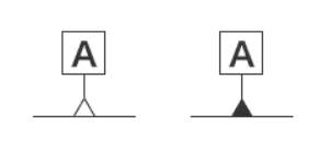
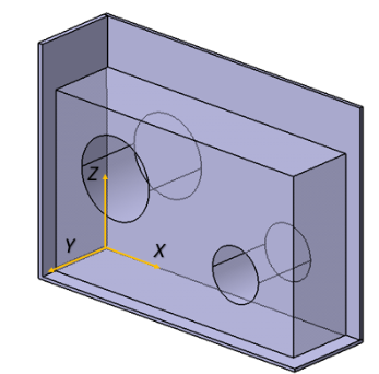
Datum symbols indicate planes, center axes, and fixed points on engineering drawings.
1. Mark on a flat surface
You can put the datum symbol directly on the part surface or its extension line. For common flat parts, the datum only works on the symbol side. For cylindrical parts, the whole circular surface is the datum.
2. Mark on the central axis
Attach the datum symbol to the diameter dimension line. This defines the central center line of the part as the datum, not the outer surface. It is often used for runout, perpendicularity, and concentricity tolerance control.
3. Mark on the hole axis or a fixed point
There are three common ways to mark the hole datum axis:
- Put the datum symbol directly on the hole outline
- Add the symbol on the leader line pointing to the hole
- Place the datum symbol inside the feature control frame of the hole
Datum vs Datum Feature:
• A datum is the ideal geometric reference derived from a datum feature.
• A datum feature is the actual physical feature on the part, such as a face, hole, slot, shaft, or edge.
So:
- Datum feature = real part feature
- Datum = ideal reference created from that feature
Simple example
If the bottom face of a block is marked as Datum A, then:
- The bottom face is the datum feature
- The perfect plane derived from it is the datum
This distinction matters a lot. Many errors begin when people treat the real surface and the theoretical datum as the same thing.
Why Are Datums Important in Engineering Drawing?
A drawing is not just a list of sizes. It is a functional relationship between features. Datums are needed because the part must be controlled in a way that reflects how it will actually work in assembly.
For example:
- A hole may need to be located on a mounting face
- A slot may need to be clocked from a side face
- A bore may need to define the part axis
- A sealing surface may need to be measured relative to a base plane
If the part is inspected only by size, the result can be misleading. A feature may be within size tolerance but still be in the wrong place relative to the functional reference. That is why a part can seem acceptable, yet fail CMM inspection or assembly.
Main Types of Datums and Their Roles
Datums can be grouped into several main types.
1. Datum Plane
A datum plane is a theoretically exact plane established from a real surface.
Example: The bottom face of a part is marked as datum A. During inspection, the part may be placed on a surface plate or simulated plane. That contact creates the theoretical datum plane.
A datum plane is often used for:
- mounting faces,
- sealing faces,
- base surfaces,
- setup faces,
- large contact surfaces,
- orientation references.
A datum plane is useful because many parts sit, mount, or seal against flat surfaces. However, the actual datum feature must be stable enough. If the surface is warped, rough, thin, or easily distorted, it may not produce repeatable measurement results.
2. Datum Center Plane
A datum center plane is established from two opposite surfaces.
Example: A part has two parallel side faces. The center plane between them is used as datum B. The real datum feature is the pair of surfaces. The datum is the ideal middle plane derived from them.
This is useful when the part is functionally centered between two sides, rather than located on one side only.
3. Datum Axis
A datum axis is a theoretically exact line established from a cylindrical feature. It may come from:
- a hole,
- a bore,
- a pin,
- a shaft,
- a cylindrical boss.
For a hole, the datum axis may be derived from a precision pin or CMM evaluation of the bore. For a shaft, the axis may be derived from a ring, chuck, V-block, or CMM measurement.
Datum axes are very important in rotating parts, locating pins, bearing bores, dowel holes, and coaxial assemblies.
4. Datum Point
A datum point is a theoretically exact point. It may be derived from a spherical feature or a defined contact point. Datum points are less common than planes and axes, but they are useful in some special locating conditions.
5. Datum Targets
A datum target is a specific point, line, or limited area used to establish a datum instead of using the entire surface. Datum targets are useful when the full surface is not suitable as a stable reference.
For example:
- The surface is warped,
- The surface is cast or forged,
- The bottom is concave,
- The feature is too large,
- The part cannot sit repeatably on the whole face,
- Only certain pads are functional contact areas.
A datum target allows the drawing to say: “Use these exact areas to establish the datum.”
This improves repeatability in CNC machining and inspection. Datum targets are often shown with a circular datum target frame. The frame includes the datum letter and target number, such as A1, A2, and A3.
What Is Datum Reference Frame (DRF)?
A Datum Reference Frame is a standard coordinate reference system used in GD&T for part checking. It is built from datums, which are ideal theoretical reference points, planes, or axes. All geometric tolerance rules follow this unified frame.
DRF Functions
- It fixes the position and posture of a workpiece by restricting all 6 degrees of freedom of the part.
- It sets unified judging standards for all dimensional and geometric tolerances on drawings.
- It unifies the inspection basis; features using the same datums in the same order are measured under the same standard.
- It guides actual part inspection by matching real part surfaces with simulated ideal datums step by step.
DRF Importance & Significance
- Ensure assembly match: DRF is designed according to real assembly logic, making qualified parts fit and work properly.
- Unify inspection standard: Avoid different test results caused by different measuring references.
- Clear datum priority: The listed order of datums decides their constraint priority to locate parts accurately.
- Guarantee production consistency: Keep finished parts consistent with design requirements; only functionally qualified products pass detection.
- Simplify CNC machining and quality testing: Provide a clear positioning basis for machining and full-range size verification.
GD&T 3-2-1 Rule and Degrees of Freedom
The 3-2-1 rule is the core GD&T geometric principle for rigid part constraint and DRF construction. It defines the minimum contact points between datum features and theoretical datum planes, and applies exclusively to planar datums with a full three-plane reference system.
A free rigid body in space has 6 degrees of freedom (DOF):
- 3 translational DOF along X, Y, Z axes
- 3 rotational DOF around X, Y, Z axes.
The 3-2-1 rule constrains all 6 freedoms step by step through three levels of datums to achieve full positioning of the part.
3-2-1 Principle
- Primary Datum (3 contact points): The functionally dominant planar primary datum contacts its theoretical plane via 3 non-collinear points, constraining 1 translational and 2 rotational DOFs for primary positioning.
- Secondary Datum (2 contact points): The secondary datum is perpendicular to the primary datum, with 2 contact points to its theoretical plane. It constrains an additional 1 translational and 1 rotational DOF to stabilize part orientation.
- Tertiary Datum (1 contact point): The tertiary datum provides 1 contact point to constrain the final translational DOF. All 6 spatial DOFs are fully constrained, achieving complete, stable part positioning.
How to Choose Datums on Engineering Drawings?
- Ease of Measurement: Adopt accessible, mating-related features as datums. Avoid hidden features to reduce errors and improve inspection efficiency.
- Feature Simplicity: Use simple, regular features (planes, edges, hole axes) for stable and precise referencing; complex irregular features are prohibited for datums.
- Reasonable Feature Size: Datum features shall be larger than measured features to prevent projection errors. Plane datums ensure a valid flatness reference, while hole datums require matched positioning to avoid amplified tilt deviation over long projection distances.
- Functional Priority Principle: Prioritize mating surfaces, mounting holes, and anti-rotation features to align tolerance design with practical part performance.
Which Features Are Constrained by Datums?
A feature is constrained by datums when its tolerance callout references one or more datum letters.
For example:
- Position tolerance of a hole relative to A | B | C.
- Perpendicularity of a face relative to datum A.
- Parallelism of a surface relative to datum B.
- Profile of a surface relative to A | B | C.
- Runout relative to datum axis A.
These features cannot be freely shifted for machining convenience. Their tolerance zones are locked to the datum reference frame.
Examples of datum-controlled features:
| Feature | Common Control | Datum Relationship |
|---|---|---|
| Dowel hole | Position | Located in the datum system |
| Bearing bore | Position, runout, perpendicularity | Aligned to functional datum |
| Mounting face | Parallelism or perpendicularity | Oriented to the datum plane |
| Sealing surface | Profile or flatness | May be controlled to datum or by form only |
| Hole pattern | Position | Pattern located to the datum reference frame |
| Rotating diameter | Runout | Controlled to datum axis |
| Machined contour | Profile | Controlled relative to the datum frame |
If a hole is dimensioned from the left datum, it must maintain its relationship to the left datum. It cannot move just because the programmer applied a global offset to make the outer shape look centered.
Which Features May Be Offset or Adjusted?
Some features may be adjusted within their allowed tolerance if they are not functionally locked to a datum in the same way.
For example:
- an outer profile with bilateral size tolerance,
- a non-critical edge,
- a cosmetic contour,
- a stock-removal boundary,
- a clearance surface,
- a feature controlled only by general tolerance.
However, even these features are not always free. Their freedom depends on the drawing.
A feature may be adjustable only if:
- The drawing does not define a fixed datum relationship for that feature,
- The adjustment does not violate another geometric tolerance,
- The adjustment does not affect assembly or function,
- The adjustment does not shift a datum-controlled feature,
- The adjustment stays within the stated size, form, orientation, or profile limits.
A common machining mistake is to treat all tolerances equally. But tolerances have a hierarchy. A general size tolerance does not override a datum-controlled GD&T requirement. If a feature is controlled by the datum structure, datum logic overrides machining convenience.
Types of Geometric Tolerance in GD&T
1. Form Tolerances
Form tolerances control the shape of a feature by itself. They usually do not use datums.
Common form controls include:
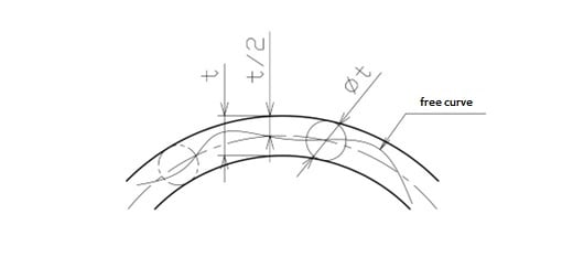
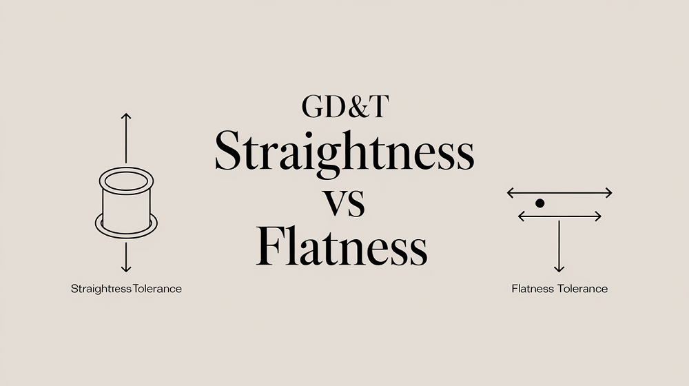
- straightness,
- flatness,
- circularity,
- cylindricity.
Example: Flatness controls how much a surface can deviate from a perfect plane. Circularity controls how round a circular cross-section must be. Cylindricity controls the full 3D form of a cylinder.
A surface can be flat but still not parallel to another surface. That is why form control and orientation control are not the same.
2. Orientation Tolerances
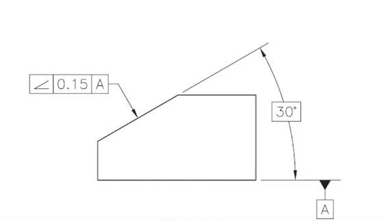
Orientation tolerances control the tilt of a feature relative to a datum.
Common orientation controls include:
- parallelism,
- perpendicularity,
- angularity.
Example: A top face may be controlled to be parallel to datum A. A hole axis may be controlled to be perpendicular to datum A.
Orientation controls do not control location by themselves. A hole can be perpendicular but still in the wrong X-Y position.
3. Location Tolerances
Location tolerances control where a feature is located.
Common location controls include:
- position,
- concentricity,
- symmetry.
In modern practical machining, positioning is very common for holes, pins, slots, and patterns. Concentricity and symmetry are often more difficult to inspect and may be misunderstood, so they should be used only when truly required.
Position tolerance is especially important because it controls the location of a feature axis, center plane, or center point relative to basic dimensions and datums.
4. Profile Tolerances
Profile tolerances control the outline or surface boundary of a feature.
There are two main types:
- profile of a line,
- profile of a surface.
Profile of a surface is very useful for complex CNC surfaces, castings, forgings, contours, sealing surfaces, and aerodynamic or molded shapes.
Depending on the callout, the profile can control size, form, orientation, and location.
5. Runout Tolerances
Runout controls variation when a feature rotates about a datum axis.
Common runout controls include:
- circular runout,
- total runout.
Runout is important for rotating parts, shafts, bearing seats, pulleys, spindles, and coaxial features.
Common International GD&T Standards
There are two major families of GD&T standards in common use:
- ASME Y14.5
- ISO GPS standards, especially ISO 1101 and ISO 5459
1. ASME Y14.5
ASME Y14.5 is the global authoritative GD&T standard for mechanical engineering. It unifies official symbols, definitions, rules, and best practices for geometric dimensioning and tolerancing, applicable to engineering drawings and digital product models. This standard only defines design geometric intent; inspection and gauging rules are specified in the separate ASME Y14.43 standard.
Core Section & Content
- Section 1: Defines standard scope, universal GD&T terms, and basic dimensioning rules.
- Section 2: Covers core tolerancing principles, including Envelope Principle, MMC, LMC, and RFS.
- Section 3: Standardizes all GD&T symbols and defines the Feature Control Frame (FCF) for formal tolerance annotation.
- Section 4: Regulates datum selection and referencing, constrains parts’ six spatial degrees of freedom to ensure accurate positioning.
- Section 5 (Form Tolerance): Controls part surface geometry (straightness, flatness, circularity, cylindricity).
- Section 6 (Orientation Tolerance): Manages feature angle relative to datums (angularity, perpendicularity, parallelism).
- Section 7 (Location Tolerance): Controls feature positional accuracy (position, concentricity, symmetry).
- Section 8 (Profile Tolerance): Governs 2D line and 3D surface profile, capable of comprehensive geometric control.
- Section 9 (Runout Tolerance): Controls surface variation of rotationally symmetric parts (circular & total runout).
2. ISO 1101
ISO 1101:2017 is the international foundational standard for geometrical product specification (GPS). It establishes the symbol language and interpretation rules for geometric dimensioning and tolerancing (GD&T) used on engineering drawings and 3D CAD models.
What It Defines
- Standardized GD&T symbols, basic concepts, tolerance zones, and specification rules for workpiece geometry
- Rules for clear, explicit geometric annotation (including visible labels and theoretically exact dimensions, TED)
- Methods for direct drawing annotation and indirect specification via 3D CAD models (per ISO 16792)
- Uniform interpretation to eliminate ambiguity between design, manufacturing, and inspection
What Is Feature Control Frame (FCF)?
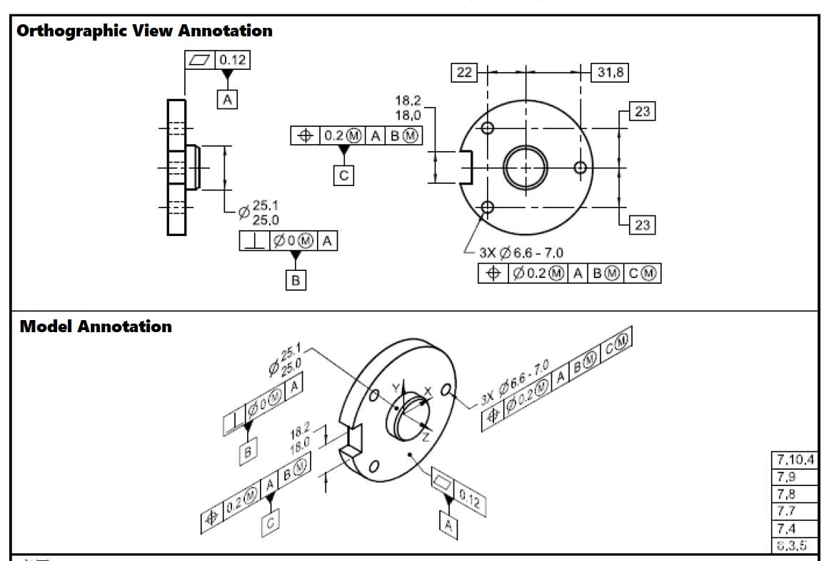
The feature control frame is the rectangular box that carries the GD&T requirement. It usually contains:
- the geometric symbol
- the tolerance value
- material condition modifier, if any
- datum references in order
A true position callout may mean:
- This hole axis must lie inside a cylindrical tolerance zone
- The zone is located between datums A, B, and C
- The feature must be evaluated after alignment to the DRF
Why order matters
The order of datums in the FCF is important:
- A is primary
- B is secondary
- C is tertiary
That order defines how the part is constrained and inspected.
If A is omitted, the whole frame can lose meaning because the part is no longer being located in the same way.
What Does Tolerance Stack-Up Mean?
Tolerance stack-up means that small variations from multiple features, operations, or parts accumulate and affect the final assembly.
A single dimension may be acceptable by itself, but the combination of many acceptable variations can still create a functional problem.
For example:
- A base face has flatness variation,
- A side datum has a perpendicularity variation,
- A hole has a position variation,
- A mating pin has size variation,
- The next part has its own location variation.
Each one may be “within tolerance,” but the assembled condition may be tight, misaligned, noisy, leaking, or impossible to assemble.
This is why datum selection is critical. Good datum choices reduce unnecessary contributors in the tolerance stack. Poor datum choices create longer tolerance chains and higher risk.
A good datum scheme should use the surfaces or features that actually locate the part in the final assembly. If the drawing uses a non-functional edge as the datum, but the assembly locates from a bore, the tolerance analysis may not represent the real product.
How Datums Are Used in CMM Inspection?
A CMM does not just measure a feature in isolation. It evaluates the feature relative to the datum reference frame.
Basic CMM logic
- Establish datum A
- Establish datum B
- Establish datum C
- Build the DRF
- Measure the controlled feature
- Compare the result to the tolerance zone
Why this matters
A part can pass a simple caliper check and still fail CMM inspection because:
- The feature is in the wrong place relative to the datum
- The axis is tilted
- The profile exceeds the zone
- The part was measured with the wrong reference logic
CMM is checking the function, not appearance.
The CMM is not asking whether the part seems centered. It is asking whether the actual feature fits inside the allowed geometric zone relative to the correct datums.
CMM Inspection Standard & Basis
CMM acceptance should be based on:
- The drawing revision,
- The stated units,
- The governing GD&T standard,
- The datum reference frame,
- The feature control frame,
- The tolerance value,
- The tolerance zone shape,
- The material condition modifier, if any,
- The actual measured feature,
- The evaluation method required by the standard or inspection plan.
For a hole position requirement, the CMM may evaluate:
- Actual hole diameter,
- Actual hole axis,
- Datum alignment,
- True theoretical hole location,
- Deviation of the actual axis from the true position,
- Bonus tolerance if MMC applies,
- final pass/fail result.
For a profile requirement, the CMM may evaluate:
- Many surface points,
- Deviation from CAD nominal geometry,
- Relationship to datums,
- Whether all measured points stay inside the profile zone.
For flatness, the CMM should evaluate the form of the surface itself, not simply report a casual best-fit number without understanding the standard requirement.
Inspection must match the drawing logic. If the drawing uses GD&T but inspection uses only simple caliper checks, the inspection may miss functional errors.
Datum Material Condition Modifiers
Material condition modifiers change how tolerance is applied.
1. MMC: Maximum Material Condition
MMC means the feature contains the most material.
For a hole:
- MMC is the smallest allowed hole size.
For a pin or shaft:
- MMC is the largest allowed pin size.
When position tolerance is applied at MMC, bonus tolerance may be allowed as the feature departs from MMC. For example, if a hole is larger than its smallest allowed size, it may have more positional freedom because assembly clearance has increased.
2. LMC: Least Material Condition
LMC means the feature contains the least material.
For a hole:
- LMC is the largest allowed hole size.
For a pin:
- LMC is the smallest allowed pin size.
LMC is less common but useful when the minimum wall thickness or edge distance must be protected.
3. RFS: Regardless of Feature Size
RFS means the geometric tolerance applies regardless of the actual feature size. There is no bonus tolerance unless the standard and callout allow it.
These modifiers must not be guessed. They must be read according to the governing standard.
Common Mistakes in CNC Machining and Design Teams
- Ignoring datum intent: People focus on the dimension but ignore the functional reference.
- Treating GD&T like decoration: GD&T is not a symbol to make drawings look advanced. It is a functional control system.
- Global offsetting without checking datum-controlled features: This is one of the biggest machining risks.
- Using the wrong standard: ASME and ISO are not always interpreted the same way.
- Confusing size with location: A hole can be the correct diameter and still be in the wrong place.
- Using visual judgment instead of inspection logic: Visual judgment cannot replace datum-based evaluation.
- Poor training: If designers, programmers, and inspectors do not share the same GD&T language, the drawing becomes a debate instead of a contract.
How to Make Sure the Part Is Qualified?
To ensure a part is actually good, not just “machined,” follow these steps.
1. Before machining
- Read the drawing carefully
- Identify the governing standard
- Identify the datums
- Identify the FCFs
- Understand which features are functional
- Identify which features can and cannot move
- Check if the part needs a datum target
2. During process planning
- Align workholding to the datum scheme
- Use a setup strategy that matches assembly logic
- Avoid shifting datum-controlled features for convenience
- Consider the stack-up across setups
- Define inspection points before cutting
3. During machining
- Hold the right datum surfaces
- Do not sacrifice location logic for size convenience
- Watch for tool deflection and clamping distortion
- Maintain datum transfer across operations
4. During inspection
- Inspect using the correct DRF
- Verify the right derived feature
- Use CMM logic that matches the drawing
- Judge pass/fail based on the standard, not on appearance
5. Before shipment
- Confirm functional fit
- Confirm assembly compatibility
- Confirm the report matches the drawing’s logic
- Confirm the part is not only dimensionally close, but also functionally correct
A part is not good just because the size looks acceptable. It is good only when it satisfies the datum system and functional geometry of the drawing.