- Home
- Machining techniques
- CNC Machining Services
- Cooperative supply services
- Designs
- Materials
- Finishing Services
- Shop
- Products
- Guide
- About Us
- Contact Us
2021.5.27
Our modern world depends on the machine shop, metal is shaped into gears, axles, pistons, sleeves, and pins. that make the airplane possible. that gives us our modern trains and provides us with the machines necessary for our national welfare. each machined piece of steel is so carefully made, that it can take its place on the assembly line, miles away from the machine shop. the gear starts as rough stock, which must be drilled, bored, and reamed to exact size on a lathe, looks like an internal tapering gear blank.
The Standard Procedure of Drilling, Boring, And Reaming
# Preparing For Drilling
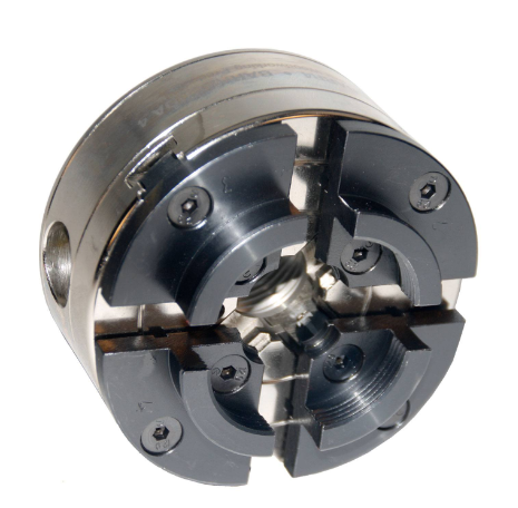
First, check the rough stock against the drawing to make sure it’s the proper size. every job has the proper steps to be followed and inspection of the drawing will show what they are in a simple form. these are the operations as planned. the first step is to cut a true finish on the face of the gear blank, the second step is drilling the hole. in the third step, a trial boring cut is made to get the correct taper. the fourth step, another trial boring cut establishes the correct taper. the fifth step brings the taper down to the rough size. the sixth step or reaming operation finishes the taper to exact size. after the operator visualizes what is to be done, the lathe is set up for the job. since most of the work on the piece is done in the center hole. this stock cannot be placed between centers, it must be held in a chuck. because the stock is raw and may be out of round, a four-jaw independent chuck of the proper size is chosen, it will hold the stock securely, the threads on the headstock spindle and in the chart cleaned and oiled since chips or dirt may damage them. a board is placed across the bed to protect the ways from damage in case the Chuck is dropped, then the Chuck is screwed on the spindle until it comes against the shoulder. in this setup, Chuck does the driving. the jaws of a Chuck are opened wide enough to receive the stop. the stock is centered approximately by checking with the concentric circles scored on Chuck’s face. although the stock may appear to be centered, the eyes cannot be trusted. further steps must be taken to get to work as near the exact center as is possible.
The lathe is started and a piece of chalk is held firmly and moved in slowly until it just touches the stalk as it revolves. when the lathe is stopped, the chop marks are found on the high side of the rough stock. the jaw opposite the chalk mark is loosened slightly, the jaw next to the chalk mark is tightened. after the stock is centered, it is ready for the facing and truing cut. a right-hand facing tool is needed for this operation, notice the position of the cutting edge, the cutting edge is set on the centerline of the stock. the cut is made deep enough to give the face of a stock a smooth service. the automatic cross speed is used to cut. when the face of the gear blank is finished cut, the work is ready for the drilling operation.
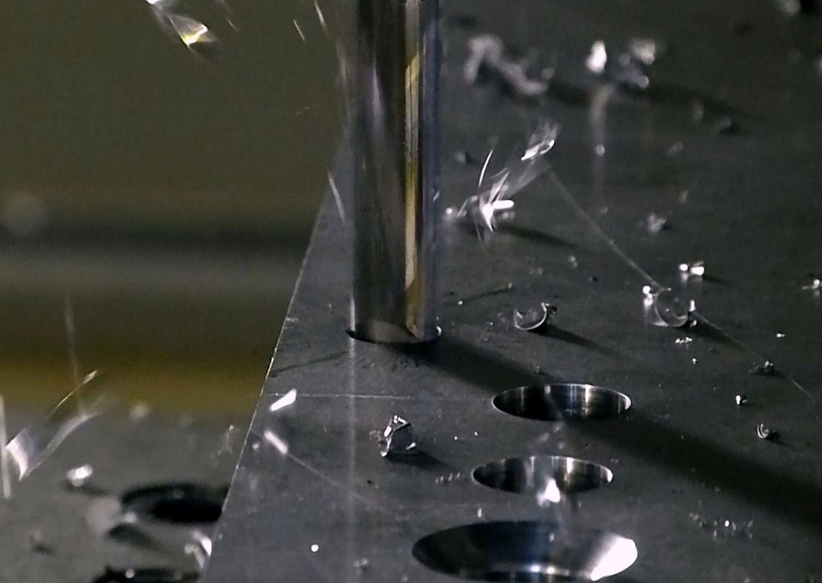
# CNC Drilling
Check the drawing for taper size, select a drill that is smaller than the small end of the taper. it must be smaller so that enough metal will be left for forming and finishing the taper. to drill a hole in the workplace the drill in the tailstock. sometimes a centering tool is used to cut a guide hole in the work. care must be taken that this guide hole is in the center. the drill is then hand-fed into this center hole. often in production, no guide or center hole is made. in this method, a bar held in the tool post is used to guide the drill as it is slowly fed into the work. once the drill has entered the work, the steel bar is removed. the lathe is started and the drill is hand-fed into the work with an easy motion. cutting oil is used for lubrication, the lathe is stopped and the drill is removed.
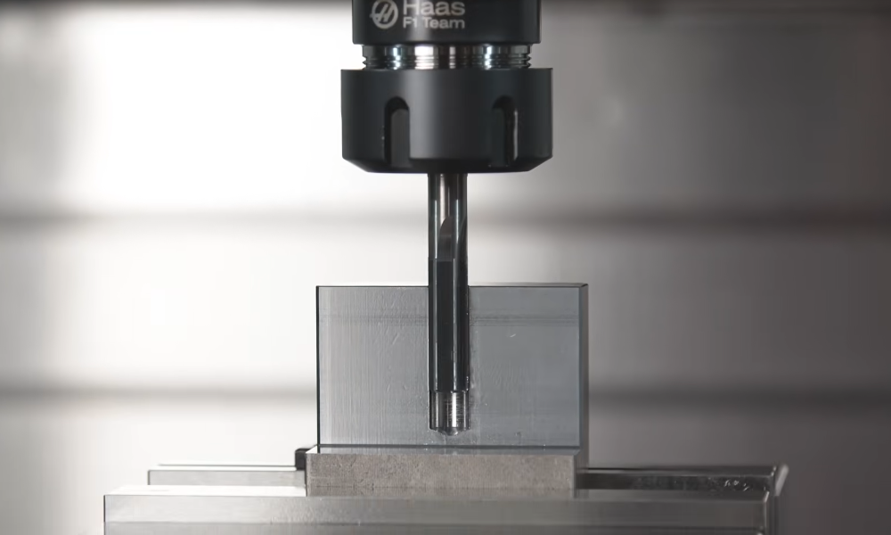
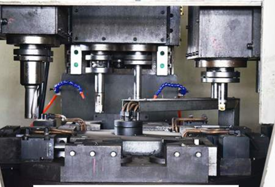
While traditional CNC drilling methods are widely used, specialized non-standard customized parts drilling processes have emerged to meet unique manufacturing challenges. As demonstrated in advanced borehole technology applications, modern CNC drilling can accommodate complex geometries and precise specifications that were previously difficult to achieve. These customized drilling processes utilize sophisticated tooling and precise control systems to create accurate, repeatable results even in challenging materials and unusual part configurations. This flexibility in drilling operations showcases how CNC technology continues to evolve beyond conventional limitations to meet specific industry demands.
# The Boring Operation
To make an internal taper accurately, the taper attachment is used. the taper attachment has a compound slide that is fastened to the lathe bed. the bolts that lock the compound rest to the crossfeed screw are removed. and the crossfeed is connected to the taper attachment. when the carriage feed is used, the cut will be made at the angle at which the taper attachment is set. before the operator sets his machine, examines the drawing. the drawing calls for a taper of one and one-half inches per foot. the taper attachment must be set to the written specification. the slide is set to one 1/2 inches per foot as shown by the graduations at the tailstock. the lock screws are now tightened to keep the slide at this setting. the drilled hole must be enlarged and tapered and this is a boring operation.
The boring tool has a long shank, since most of the cutting is done on the end it must be sharp. to support the tool properly, a V-block tool holder is used. to prevent shuttering, the boring tool should not stick out beyond the B block any farther than is necessary. the cutting edge of the boring tool is set on the centerline of the stock. the shank in the d-block is usually set parallel to the centerline of the lathe. the next step is the actual boring: the first cut is made to establish the angle, the depth of the cut is set by turning the compound feed wheel counterclockwise, this moves the tool toward the operator and into the work. the tool is fed along with the work by the automatic carriage feed. after a light trial cut is made, the taper hole is cleaned and checked to see if the angle is correct. a plug gauge is a tool for checking tapers: it is a precision instrument, the taper plug must never be turned in the hole, even a couple of turns each time a taper is checked would soon wear the gauge until it would no longer be accurate. in this case, the check shows there is a loose fit at the large end. this means the taper is too steep, the angle of the taper slide is slightly and another trial cut is made with the boring tool. the taper plug gauge fits snugly indicating that the taper angle is correct. to get the total depth of the final cuts, measure from the face of the work to the limit line which is marked on the plug. from this, the amount of metal to be removed can be figured. 5 thousandths of an inch should be allowed for reaming. the final cut with a boring tool is now made.
#Reaming The Final Cut
This is one method of reaming: the machine reamer is placed in the tail spindle, the reamer is then fed into the hole by turning the tailstock spindle wheel clockwise until the reamer bares loosely against the sides of the taper. since the reamer requires lubrication, cutting oil is used. to prevent damage, the reamer is never forced into the hole. reaming requires a slower speed than drilling, the operator feeds the reamer into the work about 3/4 of the length of a tapered part of the reamer. if the reamer is to size, the hole will be completed. if however the reamer has been sharpened and reduced in size, the hole will be undersized. a plug gauge shows this, the operator withdraws the reamer, wipes out the hole, and inserts the plug gauge. the reamer must never be turned backward in the hole, the reamer is new and to size and so the hole is now to size. the taper plug fits perfectly, the finished work is to the exact specifications called for on the working drawing.
Summarize
From the rough stock to the finished gear blank for major operations were necessary, the face of the rough stock was given a finish cut, then the work was drilled. the boring tool was used to cut the table to rough size, finally, the taper was finished with the reamer.
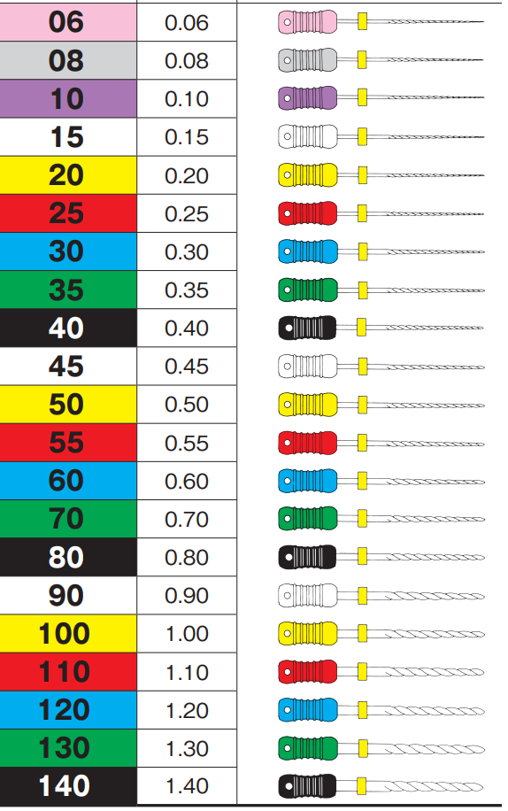 Reamer Drill Size Chart (MM/Inch) & Tolerance Chart
 Carbide & HSS Reamer Speeds and Feeds (RPM) Chart in Metric
 Guide to Boring Machining Process: Challenges, Tips and Methods of Boring Operation | CNCLATHING
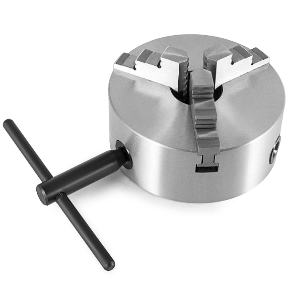
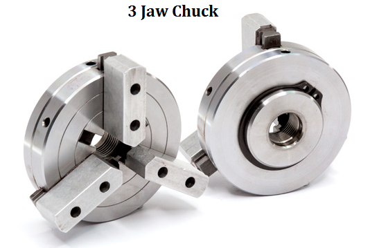 What is Three Jaw Chuck & How Does It Work | Lathe Chuck Types | CNCLATHING
 How To Install & Remove Lathe Chuck – Step By Step Guide For Lathe Chuck Installation & Removal
 Guide to CNC Chuck: Definition, Working Principle, Parts, Types and CNC vs Manual Chuck
