- Home
- Machining techniques
- CNC Machining Services
- Cooperative supply services
- Designs
- Materials
- Finishing Services
- Shop
- Products
- Guide
- About Us
- Contact Us
2020.6.20


 Properties and Application of Polytetrafluoroethylene (PTFE) | CNCLATHING
 Flow Lines In Injection Molding: How To Solve & Prevent | CNCLATHING
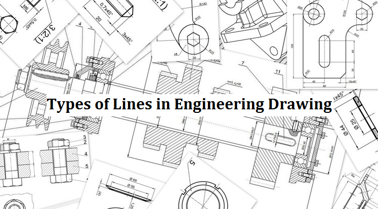
 Engineering Drawing For CNC Machining – Introduction, Applications & Drawing Instruments
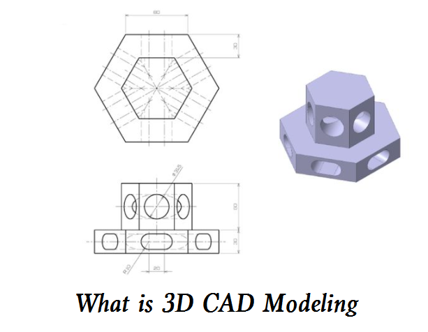 How to Convert 2D Drawing to 3D in AutoCAD – What is 3D CAD Modeling
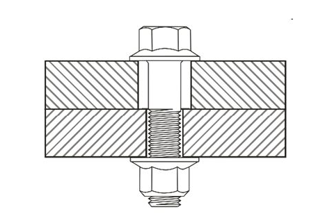 Clearance Hole Size Chart for Metric and Imperial Fasteners (Bolts, Screws & Studs)
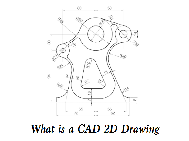 What is a CAD 2D Drawing and How to Make It? – Pros and Cons of 2D Drawing
