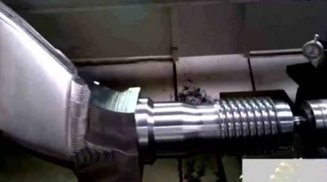
Stabbing Knife
1. Main reasons
– The front angle of the turning tool is too large, and the clearance of the x-axis screw rod of the machine tool is large.
– The turning tool is installed too high or too low.
– The workpiece is not clamped firmly.
– Excessive wear of turning tool.
– The cutting amount is too large.
2. Solution
– Reduce the rake angle of the trolley, repair the machine tool, adjust the screw clearance of the X axis, and use the screw clearance automatic compensation function of the CNC lathe to compensate the screw clearance of the X axis of the machine tool.
– The turning tool is installed too high or too low: If the turning tool is too high, when the cutting tool reaches a certain depth, the rear tool face of the turning tool is against the workpiece, increasing the friction, and even bending the workpiece, resulting in the cutting phenomenon. If it is too low, the chip is not easy to be discharged. The direction of the radial force of the turning machine is the center of the workpiece. In addition, the clearance between the traverse lead screw and the nut is too large, resulting in the constant automatic deepening of the cutting depth, thus lifting the workpiece and cutting. At this time, the height of the turning machine shall be adjusted in time to make its tip equal to the axis of the workpiece. During rough turning and semi fine turning, the tool tip position is about 1%d higher than the center of the workpiece.
– The workpiece is not clamped firmly: The rigidity of the workpiece itself cannot bear the cutting force during turning, resulting in excessive deflection, which changes the center height of the turning tool and the workpiece, resulting in a sudden increase in the cutting depth and tool pricking. At this time, the workpiece should be clamped firmly, and the tailstock center can be used to increase the rigidity of the workpiece.
– Excessive wear of turning tool: the cutting force increases, the workpiece is bent, and the tool pricking occurs. At this time, the turning tool should be polished.
– The cutting amountis too large: Select a reasonable cutting amount according to the lead size of workpiece 5 and the rigidity of workpiece.
Disorderly Buckle
1. Fault phenomenon
When the lead screw rotates once, the workpiece does not rotate by an integer.
2. Main reasons
– The synchronous drive belt of the machine spindle encoder is worn, and the synchronous true speed of the spindle cannot be detected.
– Incorrect programming of input host. The x-axis or y-axis screw is worn.
3. Solution
1) Spindle encoder synchronous belt worn
As the movement relationship between the spindle and the turning tool is controlled by the command issued by the information processing center of the machine host when turning the thread on the CNC lathe, the spindle speed is constant when turning the thread, and the moving speed of the X or Y axis can be adjusted according to the size of the workpiece lead and the spindle speed, so the center must detect the real synchronous speed of the spindle to issue the correct command to control the correct movement of the X or Y axis.
If the system cannot detect the true rotation speed of the spindle, it will send different commands to X or Y during actual turning. Then when the spindle rotates, the moving distance of the machine is not a lead, and the threads will be buckled when turning with the second tool. In this case, we only have to repair the machine and replace the spindle synchronous belt.
2) Incorrect programming input
In order to prevent disordered thread cutting, it is necessary to ensure that the turning path of the next tool coincides with the turning path of the previous tool. On ordinary cars, we use the reverse turning method to prevent disordered thread cutting.
On the numerical control lathe, we use programs to prevent disorderly screwing, that is, when preparing the processing program, we use programs to control the thread cutter to withdraw the tool after turning the previous tool, so that the starting point position of the latter tool coincides with the starting point position of the previous tool, so that the turned threads will not be disorderly screwed. Sometimes, due to the incorrect lead of the program input, disordered deduction will also occur during turning.
3) Serious wear of x-axis or y-axis screw rod
Repair the machine tool and replace the x-axis or z-axis screw rod.
Incorrect Pitch
1. Main reasons
The data transmitted back to the machine tool system by the spindle encoder is inaccurate. Excessive movement of x-axis or y-axis screw rod and main shaft. The program prepared and entered is incorrect.
2. Solution
– Inaccurate data transmitted by the spindle encoder: Repair the machine tool, replace the spindle encoder or synchronous transmission belt.
– Excessive movement of x-axis or y-axis screw rod and main shaft: Adjust the axial movement of main shaft, and the clearance of x-axis or y-axis screw rod can be compensated by the system clearance automatic compensation function.
– Check the procedure and make sure that the instruction lead in the procedure is consistent with the drawing requirements.
Incorrect Tooth Profile
1. Main reasons
Incorrect sharpening of turning tool tip, incorrect installation of turning tool, the turning tool is worn.
2. Solution
– Incorrect sharpening of turning tool tip: Sharpen and measure the angle of turning machine tip correctly. For thread turning requiring high accuracy of tooth angle, standard mechanical clamping thread cutter can be used for turning, or the thread cutter can be sharpened with a grinder.
– Incorrect installation of turning tool: When installing the tool, set the tool with the template, or install the screw thread cutter by aligning the screw thread cutter rod with the dial indicator.
– Turning tool wear: According to the actual situation of turning, reasonably select the cutting amount and timely repair the turning tool.
Analysis Of Big Fault of Thread Surface Roughness
1. Main reasons
– The tool tip produces a chip buildup.
– The tool handle is not rigid enough, causing vibration during cutting.
– The forward angle of turning tool diameter is too large.
– When cutting threads at high speed, the cutting thickness is too small or the chips are discharged in an inclined direction, and the machined tooth side surface is roughened.
– The rigidity of the workpiece is poor, and the cutting amount is too large.
– The surface roughness of turning tool is poor.
2. Solution
– When cutting with high speed steel turning tool, the cutting speed should be reduced and the cutting fluid should be selected correctly.
– Increase the section of the tool handle and reduce the extension length of the tool handle.
– Reduce the forward angle of the tool diameter of the trolley.
– When cutting thread with high-speed steel, the chip thickness of the last tool is generally greater than 0.1mm, and the chip is discharged along the vertical axis.
– Select reasonable cutting parameters.
– The surface roughness of the cutting edge of the tool shall be 2-3 grades lower than that of the machined surface of the part.
 7018 Welding Rod Specifications: Properties, Amperage (Sizes) Chart, Uses, 7014 vs 7018 Electrodes
 Spindle Bearing of Lathe – Adjustment of Radial Clearance and Axial Clearance
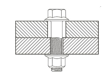 Clearance Hole Size Chart for Metric and Imperial Fasteners (Bolts, Screws & Studs)
 Spring Material Types (Properties, Grades, Uses) & Best Selection for Your Project
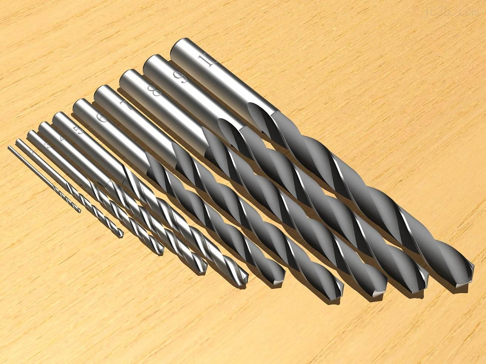 What are Drill Tip Angle and Helix Angle in CNC Machining?
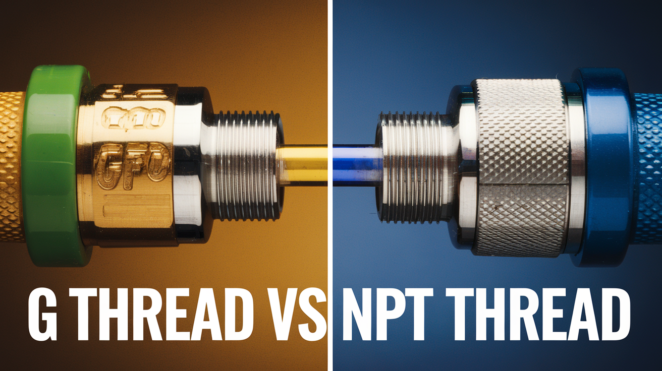 G Thread vs NPT: Differences in Dimensions, Uses, Standard Specs
