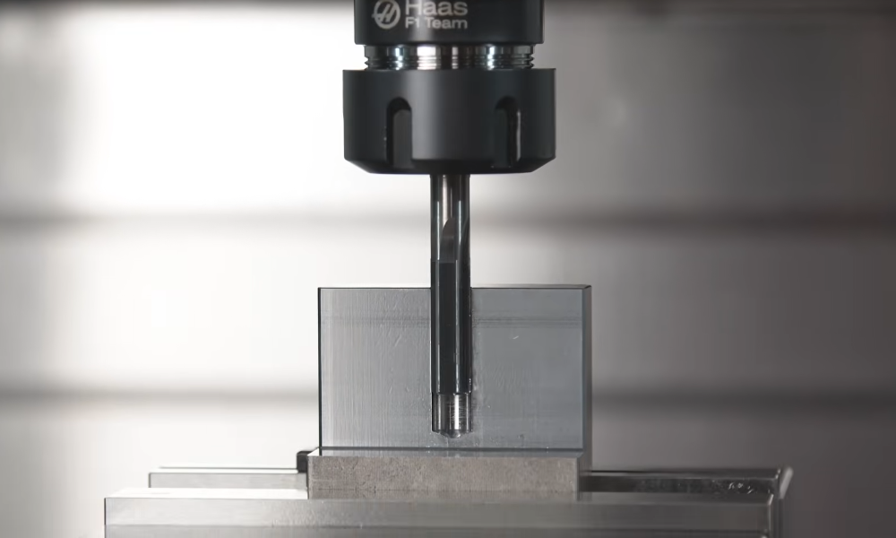
Selection of Cutting Tools
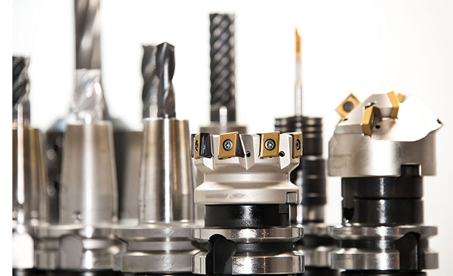
Choosing more reasonable cutting tools can directly improve production efficiency. The cutting of aluminum alloy materials does not require high-cutting tool materials. Generally, cemented carbide milling cutters can be used, and the coating can use uncoated or diamond coating. In rough machining, because there is no need to consider the problems of accuracy and quality, metal materials can be cut efficiently to the greatest extent. Therefore, large diameter tools can be selected to reduce the number of tool walking and shorten the time of tool walking.
In addition, in rough machining, try to choose dense gear tools to replace sparse gear tools, which can increase the feed per revolution, and the cutting speed can be increased at the same speed. In finish machining, in addition to the problem of efficient removal of materials, we should also fully consider the control of stress and deformation of thin-walled components in cutting.
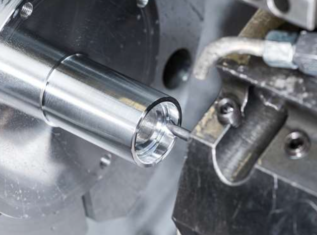
Cemented carbide tools should be selected for the finishing of high-strength aluminum alloy thin-walled parts. The rake angle of the tool should not be too small, otherwise, the cutting deformation and friction will increase, the wear of the rake face will increase, and the service life of the tool will be reduced. In addition, the arc radius of the tooltip should be selected appropriately, and the tool teeth should not be too dense, which is convenient for chip discharge, is conducive to further improving the feed rate, preventing cold hardening layer, and extending the service life of the tool.
Selection of Tool Path
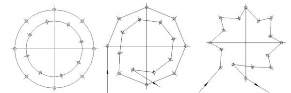
One of the more effective ways to increase speed and efficiency is to optimize the tool path. In high-speed cutting, it is necessary to ensure the directionality of the tool path, that is, the tool path should be simplified as much as possible, with fewer turning points, and the path should be as smooth as possible to reduce rapid steering; Reduce the empty cutting time and increase the proportion of cutting time in the whole workpiece as much as possible; Loop cutting should be used as far as possible, and by not interrupting the cutting process and tool path, the number of cutting in and cutting out of the tool should be reduced, so as to obtain a stable, efficient and high-precision cutting process.
In the high-speed machining of large complex surfaces of integral structural parts, when the curvature of the surface changes greatly, the direction of the maximum curvature radius should be taken as the optimal cutting direction; When the curvature of the surface changes little, the influence of the radius of curvature on the cutting direction is weakened, and the cutting direction with the longest average length of a single tool path should be selected.
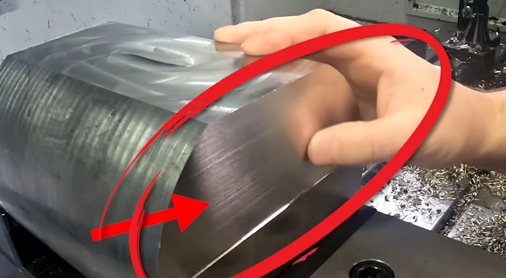
When machining inclined planes, if horizontal cutting is adopted, the cutting distance of each section is very short. During the cutting process, the spindle needs to be frequently reversed, and the cutting stability is poor. Moreover, because the cutting is inclined planes, horizontal cutting requires the linkage of the X or Y axis and Z axis, which is not conducive to the improvement of cutting speed.
Therefore, for this kind of inclined surface processing, the tool path should be arranged parallel to the longest inclined edge as far as possible, which not only has the longest tool path and the least number of commutations, but also the single tool path is only cutting in the XY plane, and the movement in the z-axis direction is arranged outside the workpiece contour, which can reduce the tool damage even under high-speed cutting.
Selection of Cutting Parameters
In rough machining, it is generally possible to choose a high feed rate and appropriate large cutting depth, coupled with “high-power” high-efficiency cutting with medium cutting speed, so as to achieve high material removal rate and greatly improve production efficiency. For finish machining, only increasing the speed and the number of teeth is feasible, and increasing the feed rate per tooth may reduce the surface accuracy, produce residual stress and cause deformation. Therefore, light cutting and fast cutting with high cutting speed and low feed per tooth are often used to ensure the improvement of production efficiency and the accuracy and surface quality of products.
Cutting parameters can be determined by cutting finite element analysis and cutting tests. The cutting test can be designed within the optional range of parameters obtained by finite element analysis. Taking cutting efficiency, surface roughness, and machined surface morphology as the evaluation criteria, the optimal cutting parameters are finally selected.
 How To Reduce & Stop Chatter Vibration in CNC Milling/Turning/Drilling/Grinding Lathe?
 CNC Machining Cutting Path – Cutting Path Principles And Designs You Need To Know
 Spring Material Types (Properties, Grades, Uses) & Best Selection for Your Project
 Top 12 CNC Machining & Programming Experiences | CNCLATHING
 What is HVOF Coating – HVOF Thermal Spray Process, Materials, Benefits, Machine, Applications
 Carbide & HSS Reamer Speeds and Feeds (RPM) Chart in Metric
