
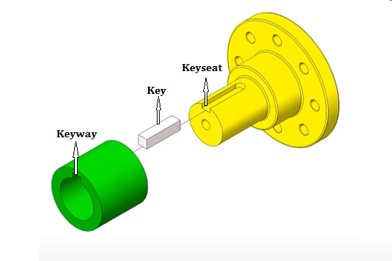
Keyed connections are achieved by cutting keyways on the shaft and hub and inserting a component called a “key”. Although small in size, the shaft key plays a significant role in mechanical transmission. A key is a mechanical element used to fix rotating shafts and gears. It is primarily used to transmit torque by securing components circumferentially on the shaft. Some keys also provide axial fixation or allow for axial movement, such as the connection between gears and shafts in reducers. While not a prominent part, keys are crucial in power transmission. So today, let’s take a close look at the Shaft Key, by talking about its types, sizes, materials, and design!
What is a Shaft Key?
Shaft key, also known as motor key, is a short bar that connects two rotating parts (typically a shaft and a hub), made from high-strength materials to transmit torque. Its function is to unite two parts into a single rotating body while allowing rotation along the axis without slipping or misalignment, ensuring transmission precision and reliability. Shaft keys are commonly used in mechanical systems such as automobiles, motorcycles, agricultural machinery, and construction equipment.
Shaft Key Types (Diagram, Features & Uses)
In various types of mechanical transmission, different types of keys play important roles in machine design and application. The basic concepts of keyed connections include flat keys, Woodruff keys, taper keys, and tangent keys, each with its own characteristics and application scope. Below, we will explore them in detail by presenting the diagram, features, and application of each shaft key type:
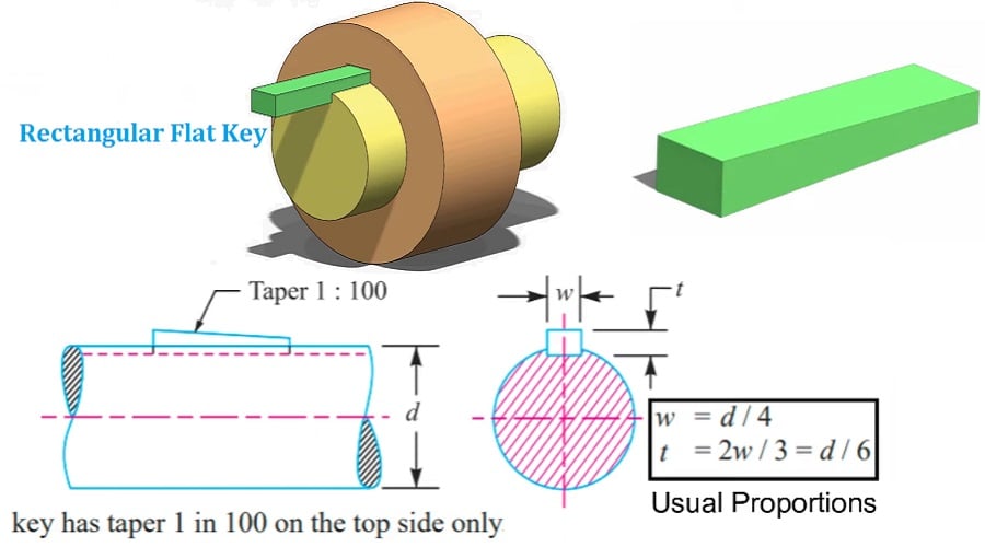
1. Flat Key (Parallel Sunk Key)
The standard flat key, aka parallel key, is a type of sunk key, used for fixed connections, with no relative axial movement between the shaft and hub. Both side surfaces are working surfaces, while there is clearance between the top surface and the bottom of the hub keyway. During operation, torque is transmitted by the compression of the shaft keyway, key, and hub keyway side surfaces. It is a taperless rectangular or square key, used where the hub needs to slide along the shaft. The flat shaft key is easy to manufacture, convenient for assembly and disassembly, good alignment between the shaft and shaft-mounted components, but cannot fix axial movement of the shaft-mounted component
The standard flat keys can be divided into three types based on the sunk: rounded end (A), square end (B), rectangular end, single rounded end (C):
- Rectangular Flat Sunk Key
- Square Sunk Key

- Round Sunk Key (double-round or single-round sided)
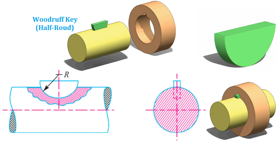
2. Woodruff Key (Half Moon Sunk Key)
Woodruff key comes with a half-moon shape, accommodates itself to any taper in the hub. Its extra depth in the shaft prevents any tendency to turn over in the keyway, but the depth of the keyway weakens the shaft. The Woodruff key is generally used in conjunction with a tapered shaft journal to transmit torque. The key slot is machined with a milling cutter of the same shape as the half-moon key, allowing it to swing around its geometric center in the slot. The key’s side surfaces are the working surfaces, transmitting torque through side compression. The keyway is milled with a disk-shaped cutter, and the key itself is semicircular. The half-round shaped key is good for manufacturability, easy assembly, and especially suitable for tapered shaft end connections. But the shaft slot significantly reduces the shaft’s strength; only suitable for light-load connections.
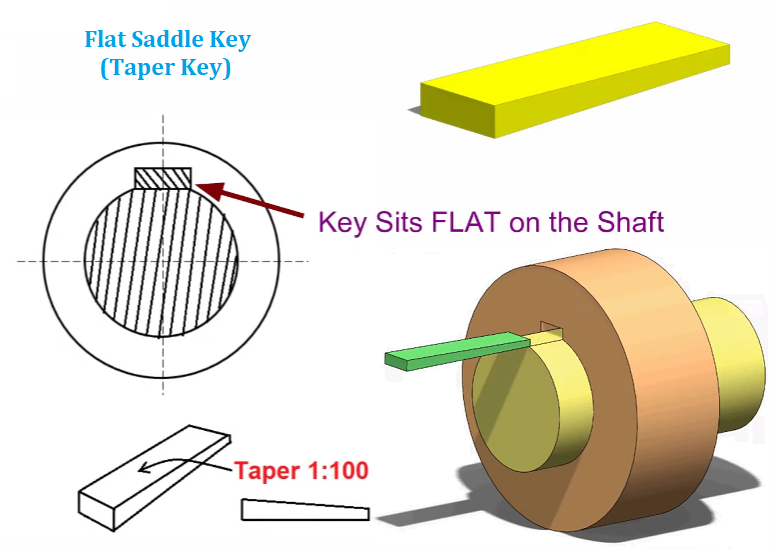
3. Saddle Keys (Taper Key)
The working surfaces of a taper key are on its upper and lower surfaces. Its top surface has a 1:100 taper, and the bottom surface of the hub keyway is also designed with this taper. When the taper key is inserted into the shaft and hub keyways, significant pre-tightening force is generated on its surfaces. During operation, the taper key mainly relies on friction to transmit torque and can withstand unidirectional axial force. However, it may cause eccentricity between the shaft and hub, making it more suitable for connections where centering accuracy is not critical, the load is stable, and the speed is low.
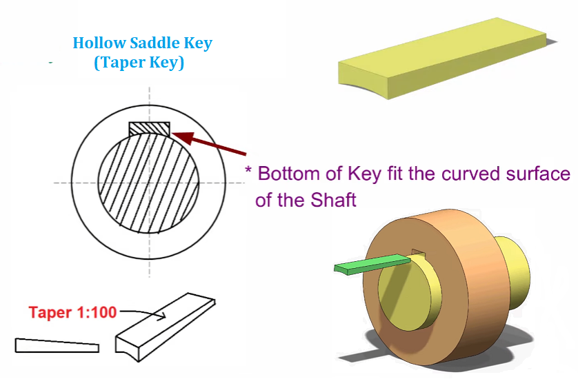
Furthermore, taper keys can be further divided into standard taper keys, hollow saddle keys, and gib-head taper keys.
- Flat Saddle Key – sits flat on the shaft
- Hollow Saddle Key – the bottom of the key fits the curved surface of the shaft
- Gib-Head Saddle Key – Features a hook for easy removal
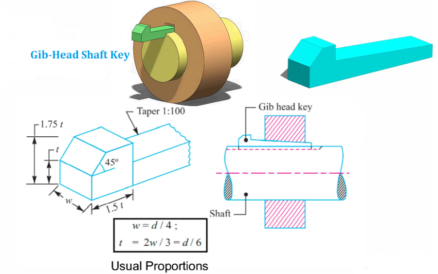
4. Gib-Head Key (Sunk Key)
The gib-head taper key is a special type of taper key, with a hook-shaped head designed to secure it more effectively in the shaft and hub keyways. The gib head facilitates easy removal of the key. This design not only enhances the stability of the connection but also reduces eccentricity between the shaft and hub to a certain extent, thereby improving the precision of the connection. Therefore, gib-head taper keys are particularly suitable for applications requiring high centering accuracy and secure connections, such as mechanical assemblies under high-speed rotation and heavy-duty conditions.
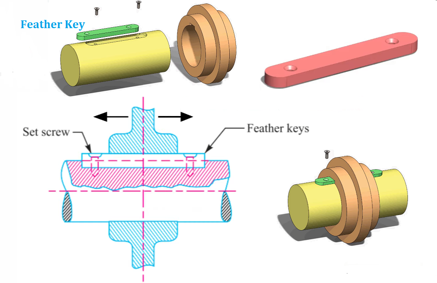
5. Feather Key (Sunk Key)
Feather Key is fitted either to the shaft or hub and also permits axial movement. The side surfaces of the key are the working faces; it transmits force through the sides, provides good alignment, and is easy to assemble and disassemble. It does not provide axial fixation. The key is fixed to the shaft using bolts, and a central threaded hole is used to remove the key. It is used in situations where the shaft component moves slightly along the shaft, such as sliding gears in gearboxes.
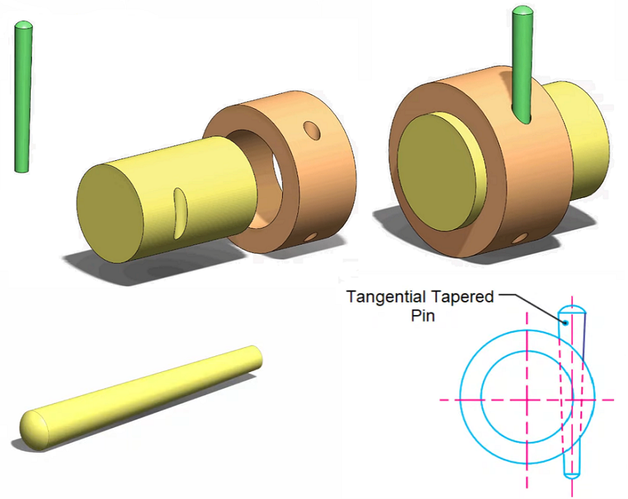
6. Dowel Key (Round Shaft Key)
Dowel key with cylinder body, fits into holes drilled in both the hub and shaft; most suitable for low-power drives. The cylindrical key is a common motor shaft key form. It is cylindrical and matches the grooves in the motor shaft and the transmission component. It is easy to install and can bear considerable torque. Dowel keys can also be designed as straight or tapered pins to meet different requirements.
- Straight Pin Dowel Key
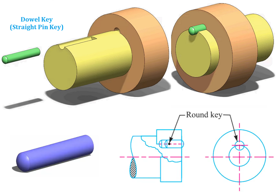
- Tapered Pin Down Key
7. Tangent Key
Tangent shaft key fits into the keyways of both the hub and the shaft; it is used in pairs at right angles to each other. Each key withstands torque in one direction only and is used in large, heavy-duty shafts. Composed of two wedge keys with a 1:100 taper, the top and bottom surfaces together form the working face, capable of transmitting large torque. A single pair of tangent keys can only transmit torque in one direction, while two pairs arranged at 120°–135° are used for bidirectional torque. These are used in high-load applications where centering is not critical. Tangent keys generate torque through tangential pressure and can also bear small unidirectional axial forces.
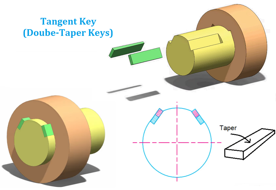
They are mainly used in situations that require only unidirectional torque transmission, or in bidirectional cases, two pairs of tangent keys are arranged at a certain distance. Due to their ability to transmit large torque, tangent keys are commonly used in heavy machinery.
8. Spline Keys
Shaft + Integrated Key = Spline Shaft, which allows axial movement (commonly used in sliding gear transmissions). A splined connection consists of multiple evenly distributed key teeth around the shaft and the hub hole, with the tooth sides acting as the working surfaces. This type of connection provides high load capacity, good centering, and guiding performance, with minimal weakening of shaft and hub strength. It is especially suitable for high-load, high-precision centering connections that frequently require sliding, such as sliding gears in transmissions. Splines can be classified into rectangular splines, triangular splines, and involute splines based on tooth shape.
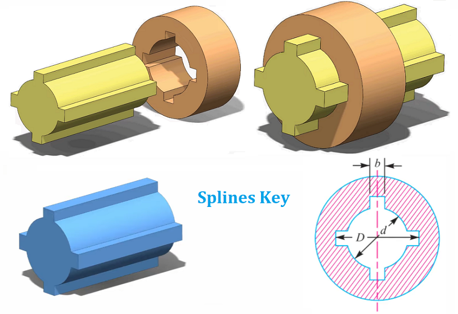
- Rectangular Spline: Easy to manufacture using milling, hobbing, broaching, or shaping. After grinding, high precision is achievable. Standards define two series: light-duty (for low loads), and medium-duty (for moderate loads). Widely used in aviation, automotive, tractors, machine tools, agricultural machinery, and general mechanical transmission devices.
- Involute Spline: Has an involute tooth profile. Under load, radial forces provide self-centering, ensuring even tooth stress, high strength, and long lifespan.Manufacturing is the same as gears, allowing high precision and interchangeability. Standard pressure angles αD are 30°, 37.5°, and 45°, used in high-load, high-precision centering, and large-size connections.
Shaft Key & Keyway Size Charts (Dimensions, Tolerances)
To ensure a tight fit between shaft keys and other components, they must meet standard dimensions:
- Diameter: Should equal or be slightly smaller than the corresponding hole diameter, typically 0.01–0.05 mm smaller
- Length: Should be slightly longer than the distance between the connected parts. Generally, the key length equals the thickness of the connecting part plus 1–2 mm
- Fillet Radius: To prevent damage or cracking due to sharp edges, radii of 0.5–1 mm should be used at both ends
- Tolerances: To ensure a tight fit, manufacturing tolerances are controlled within grades h6. h7. or h8
In order to help you better understand the dimensions of shaft keys and quickly obtain some common dimension specifications, we list the dimension tables for common shaft key types below:
Flat Key Size Chart (Parallel Shaft Key & Keyway Dimensions)
| Shaft Diameter d | Nominal Key Size | Shaft Slot Depth t₁ | Key Slot Depth t₂ | Corner Radius | ||||||
|---|---|---|---|---|---|---|---|---|---|---|
| b (h9) | h (h11) | c or r | L (h14) | Nom. | Tolerance | Nom. | Tolerance | Min | Max | |
| 6–8 | 2 | 2 | 0.16–0.25 | 6–20 | 1.2 | + | 1.0 | +0.1 | 0.08 | 0.16 |
| >8–10 | 3 | 3 | 6–36 | 1.8 | 0 | 1.4 | 0 | |||
| >10–12 | 4 | 4 | 6–36 | 2.0 | 0 | 1.8 | 0 | |||
| >12–17 | 5 | 5 | 0.25–0.4 | 14–56 | 2.8 | 0 | 2.3 | 0 | 0.16 | 0.25 |
| >17–22 | 6 | 6 | 14–70 | 3.5 | 0 | 2.8 | 0 | |||
| >22–30 | 8 | 7 | 18–90 | 4.0 | + | 3.3 | +0.2 | |||
| >30–38 | 10 | 8 | 0.4–0.6 | 22–100 | 5.0 | 0.2 | 3.9 | 0 | 0.25 | 0.4 |
| >38–44 | 12 | 8 | 28–140 | 5.0 | 0 | 3.3 | 0 | |||
| >44–50 | 14 | 9 | 36–160 | 5.5 | 0 | 3.8 | 0 | |||
| >50–58 | 16 | 10 | 45–180 | 6.3 | 0 | 4.3 | 0 | |||
| >58–65 | 18 | 11 | 50–200 | 7.0 | 0 | 4.4 | 0 | |||
| >65–75 | 20 | 12 | 0.6–0.8 | 56–250 | 7.5 | 0 | 5.4 | 0 | 0.4 | 0.6 |
| >75–85 | 22 | 14 | 63–250 | 9.0 | 0 | 5.4 | 0 | |||
| >85–95 | 25 | 14 | 70–280 | 9.0 | 0 | 5.4 | 0 | |||
| >95–110 | 28 | 16 | 80–320 | 10.0 | 0 | 6.4 | 0 | |||
| >110–130 | 32 | 18 | 90–360 | 11.0 | 0 | 7.4 | 0 | |||
| >130–150 | 36 | 20 | 1.0–1.2 | 100–400 | 12.0 | + | 8.4 | +0.3 | 0.7 | 1.0 |
| >150–170 | 40 | 22 | 100–400 | 13.0 | 0.3 | 9.4 | 0 | |||
| >170–200 | 45 | 25 | 110–450 | 15.0 | 0 | 10.4 | 0 | |||
| >200–230 | 50 | 28 | 125–500 | 17.0 | 11.4 | |||||
| >230–260 | 56 | 28 | 1.6–2.0 | 140–500 | 20.0 | 12.4 | 1.2 | 1.6 | ||
| >260–290 | 63 | 32 | 160–500 | 20.0 | 12.4 | |||||
| >290–330 | 70 | 36 | 180–500 | 22.0 | 14.4 | |||||
| >330–380 | 80 | 40 | 2.5–3.0 | 200–500 | 25.0 | 15.4 | 2.0 | 2.5 | ||
| >380–440 | 90 | 45 | 220–500 | 28.0 | 17.4 | |||||
| >440–500 | 100 | 50 | 250–500 | 31.0 | 19.5 | |||||
Woodruff Key Size Chart (Half Moon Shaft Key & Keyway Dimensions)
| Key Size (b×h×D) | Width b | Height h | Diameter D | Chamfer or Radius s | ||||
|---|---|---|---|---|---|---|---|---|
| Nominal | Tolerance | Nominal | h12 | Nominal | h12 | Min | Max | |
| 1×1.4×4 | 1 | — | 1.4 | 0 | 4 | −0.120 | — | — |
| 1.5×2.6×7 | 1.5 | — | 2.6 | −0.10 | 7 | 0 | — | — |
| 2×2.6×7 | 2 | — | 2.6 | 0 | 7 | 0 | — | — |
| 2×3.7×10 | 2 | — | 3.7 | 0 | 10 | −0.150 | — | — |
| 2.5×3.7×10 | 2.5 | — | 3.7 | −0.12 | 10 | 0 | — | — |
| 3×5×13 | 3 | — | 5 | 0 | 13 | 0 | — | — |
| 3×6.5×16 | 3 | — | 6.5 | 0 | 16 | −0.180 | — | — |
| 4×6.5×16 | 4 | 0 | 6.5 | 0 | 16 | 0 | 0.16 | 0.25 |
| 4×7.5×19 | 4 | −0.025 | 7.5 | 0 | 19 | −0.210 | 0.25 | 0.40 |
| 5×6.5×16 | 5 | — | 6.5 | 0 | 16 | 0 | 0.25 | 0.40 |
| 5×7.5×19 | 5 | — | 7.5 | −0.15 | 19 | 0 | 0.25 | 0.40 |
| 5×9×22 | 5 | — | 9 | 0 | 22 | 0 | 0.25 | 0.40 |
| 6×9×22 | 6 | — | 9 | 0 | 22 | 0 | 0.25 | 0.40 |
| 6×10×25 | 6 | — | 10 | 0 | 25 | −0.210 | 0.40 | 0.60 |
| 8×11×28 | 8 | — | 11 | 0 | 28 | 0 | 0.40 | 0.60 |
| 10×13×32 | 10 | — | 13 | −0.18 | 32 | 0 | 0.60 | 0.90 |
Saddle Key Size Chart (Standard Flat Taper Shaft Key & Keyway Dimensions)
| Width b | b Tolerance (h8) | Height h | h Tolerance (h11) | Chamfer or Radius c or r | ||
|---|---|---|---|---|---|---|
| Basic Size | Upper Limit | Basic Size | Upper Limit | |||
| 2 | 0 | −0.014 | 2 | 0 | −0.090 | 0.16–0.25 |
| 3 | 0 | −0.014 | 3 | 0 | −0.090 | |
| 4 | 0 | −0.018 | 4 | 0 | −0.090 | |
| 5 | 0 | −0.018 | 5 | 0 | −0.090 | 0.25–0.40 |
| 6 | 0 | −0.022 | 6 | 0 | −0.090 | |
| 8 | 0 | −0.027 | 7 | 0 | −0.090 | |
| 10 | 0 | −0.027 | 8 | 0 | −0.090 | 0.40–0.60 |
| 12 | 0 | −0.033 | 9 | 0 | −0.090 | |
| 14 | 0 | −0.033 | 10 | 0 | −0.090 | |
| 15 | 0 | −0.033 | 10 | 0 | −0.090 | 0.60–0.80 |
| 16 | 0 | −0.033 | 10 | 0 | −0.110 | |
| 18 | 0 | −0.033 | 12 | 0 | −0.110 | |
| 20 | 0 | −0.033 | 14 | 0 | −0.110 | 1.60–2.00 |
| 22 | 0 | −0.033 | 14 | 0 | −0.110 | |
| 25 | 0 | −0.040 | 16 | 0 | −0.130 | 2.50–3.00 |
| 28 | 0 | −0.040 | 16 | 0 | −0.130 | |
| 30 | 0 | −0.046 | 18 | 0 | −0.130 | |
| 32 | 0 | −0.046 | 20 | 0 | −0.130 | |
| 36 | 0 | −0.046 | 22 | 0 | −0.130 | |
| 40 | 0 | −0.054 | 25 | 0 | −0.160 | |
| 45 | 0 | −0.054 | 28 | 0 | −0.160 | |
| 50 | 0 | −0.054 | 32 | 0 | −0.160 | |
18, 20, 22, 25, 28, 32, 36, 40, 45, 50, 56, 63, 70, 80, 90, 100, 110, 125, 140, 160, 180, 200, 220, 250, 280, 315, 355, 400, 450, 500
Gib-Head Key Size Chart (Gib-Head Taper Shaft Key & Keyway Dimensions)
| Width b | Tolerance (h8) | Height h | Tolerance (h11) | Head Height h₁ | Chamfer or Radius c or r | ||
|---|---|---|---|---|---|---|---|
| Basic | Limit | Basic | Limit | ||||
| 4 | 4 | −0.018 | 4 | 0 | −0.075 | 10 | 0.16–0.25 |
| 5 | 5 | −0.018 | 5 | 0 | −0.075 | 12 | |
| 6 | 6 | −0.022 | 6 | 0 | −0.090 | 14 | |
| 8 | 8 | −0.022 | 7 | 0 | −0.090 | 16 | 0.25–0.40 |
| 10 | 10 | −0.027 | 8 | 0 | −0.090 | 18 | |
| 12 | 12 | −0.027 | 9 | 0 | −0.090 | 20 | |
| 14 | 14 | −0.027 | 10 | 0 | −0.090 | 22 | 0.40–0.60 |
| 16 | 16 | −0.033 | 10 | 0 | −0.110 | 25 | |
| 18 | 18 | −0.033 | 12 | 0 | −0.110 | 28 | |
| 20 | 20 | −0.033 | 14 | 0 | −0.110 | 32 | 0.60–0.80 |
| 22 | 22 | −0.033 | 14 | 0 | −0.110 | 36 | |
| 25 | 25 | −0.040 | 16 | 0 | −0.130 | 40 | 1.60–2.00 |
| 28 | 28 | −0.040 | 16 | 0 | −0.130 | 45 | |
| 30 | 30 | −0.046 | 18 | 0 | −0.130 | 50 | |
| 32 | 32 | −0.046 | 20 | 0 | −0.130 | 56 | |
| 36 | 36 | −0.046 | 22 | 0 | −0.130 | 63 | |
| 40 | 40 | −0.054 | 25 | 0 | −0.160 | 70 | 2.50–3.00 |
| 45 | 45 | −0.054 | 28 | 0 | −0.160 | 80 | |
18, 20, 22, 25, 28, 32, 36, 40, 45, 50, 56, 63, 70, 80, 90, 100, 125, 140, 160, 180, 200, 220, 250, 280, 320, 360, 400, 450, 500
Tangent Key Size Chart (Standard Tangential Shaft Key & Keyway Dimensions)
| Shaft Diameter d | Key | Keyway Depth | Keyway Width | Chamfer C | Radius r | |||||
|---|---|---|---|---|---|---|---|---|---|---|
| Thickness h | Width b (±h11) | Shaft t1 | Hub t2 | Shaft b1 | Hub b2 | Min | Max | Min | Max | |
| 60 | 18 | −0.090 | 7.0 | 7.3 | 19.3 | 19.6 | 0.6 | 0.8 | — | — |
| 65 | 20 | −0.090 | 8.0 | 8.3 | 20.1 | 20.4 | 0.6 | 0.8 | — | — |
| 70 | 22 | −0.110 | 8.0 | 8.3 | 21.0 | 21.3 | 0.6 | 0.8 | — | — |
| 75 | 25 | −0.110 | 9.0 | 9.3 | 23.2 | 23.5 | 0.6 | 0.8 | — | — |
| 80 | 28 | −0.090 | 10.0 | 10.3 | 24.0 | 24.4 | 0.8 | 1.0 | — | — |
| 85 | 28 | −0.090 | 10.0 | 10.3 | 24.8 | 25.2 | 0.8 | 1.0 | — | — |
| 90 | 30 | −0.090 | 10.0 | 10.3 | 26.7 | 27.0 | 0.8 | 1.0 | — | — |
| 100 | 32 | −0.110 | 11.0 | 11.4 | 28.0 | 28.4 | 1.0 | 1.2 | — | — |
| 110 | 36 | −0.110 | 12.0 | 12.4 | 31.0 | 31.4 | 1.0 | 1.2 | — | — |
| 120 | 40 | 0 | 14.0 | 14.4 | 34.6 | 35.1 | 1.6 | 2.0 | 1.0 | 1.2 |
| 140 | 45 | 0 | 16.0 | 16.4 | 37.7 | 38.3 | 1.6 | 2.0 | 1.0 | 1.2 |
| 160 | 50 | 0 | 18.0 | 18.4 | 42.0 | 42.8 | 1.6 | 2.0 | 1.0 | 1.2 |
| 200 | 56 | 0 | 20.0 | 20.4 | 49.6 | 50.3 | 2.0 | 2.5 | 1.6 | 2.0 |
| 250 | 63 | −0.130 | 22.0 | 22.4 | 59.9 | 60.6 | 2.5 | 3.0 | 2.0 | 2.5 |
| 315 | 70 | 0 | 28.0 | 28.4 | 72.1 | 72.8 | 3.0 | 4.0 | — | — |
| 400 | 80 | −0.160 | 36.0 | 36.4 | 93.2 | 94.0 | 3.0 | 4.0 | 3.0 | 4.0 |
| 500 | 100 | −0.220 | 50.0 | 50.5 | 125.9 | 126.6 | 5.0 | 7.0 | — | — |
| 630 | 140 | −0.190 | 63.0 | 63.5 | 189.0 | 189.7 | 5.0 | 7.0 | 3.0 | 4.0 |
| 800 | 180 | 0 | 80.0 | 80.5 | 240.0 | 240.7 | 7.0 | 9.0 | — | — |
| 1000 | 200 | −0.220 | 100.0 | 100.5 | 300.0 | 300.7 | 7.0 | 9.0 | — | — |
Splines Key Size Chart (Rectangle Splines Key & Keyway Dimensions)
| Shaft Diameter d | Light Series | Medium Series | ||||||||
|---|---|---|---|---|---|---|---|---|---|---|
| Specification N × d × D × B | Chamfer c | Radius r | d₁min | αmin | Specification N × d × D × B | Chamfer c | Radius r | d₁min | αmin | |
| 11 | 6×11×14×3 | 0.2 | 0.1 | — | — | |||||
| 13 | 6×13×16×3.5 | 14.4 | 1.0 | |||||||
| 16 | 6×16×20×4 | 16.6 | 1.0 | |||||||
| 18 | 6×18×22×5 | 0.3 | 0.2 | 19.5 | 2.0 | |||||
| 21 | 6×21×25×5 | 21.2 | 2.0 | |||||||
| 23 | 6×23×26×6 | 0.2 | 0.1 | 22 | 3.5 | 6×23×28×6 | 21.2 | 1.2 | ||
| 26 | 6×26×30×6 | 24.5 | 3.8 | 6×26×32×6 | 23.6 | 1.2 | ||||
| 28 | 6×28×32×7 | 26.6 | 4.0 | 6×28×34×7 | 25.8 | 1.4 | ||||
| 32 | 6×32×36×6 | 0.3 | 0.2 | 30.2 | 2.7 | 8×32×38×6 | 29.4 | 1.0 | ||
| 36 | 8×36×40×7 | 34.4 | 3.5 | 8×36×42×7 | 0.4 | 0.3 | 33.4 | 1.0 | ||
| 42 | 8×42×46×8 | 40.5 | 5.0 | 8×42×48×8 | 39.4 | 2.5 | ||||
| 46 | 8×46×50×9 | 44.6 | 5.7 | 8×46×54×9 | 42.6 | 1.4 | ||||
| 52 | 8×52×58×10 | 49.6 | 4.8 | 8×52×60×10 | 48.6 | 2.5 | ||||
| 56 | 8×56×62×10 | 0.4 | 0.3 | 53.6 | 6.5 | 8×56×65×10 | 52.0 | 2.5 | ||
| 62 | 8×62×68×12 | 59.7 | 7.3 | 8×62×72×12 | 0.5 | 0.4 | 57.7 | 2.4 | ||
| 72 | 10×72×78×12 | 69.6 | 7.3 | 10×72×82×12 | 67.7 | 1.0 | ||||
| 82 | 10×82×98×12 | 79.3 | 8.5 | 10×82×92×12 | 77.0 | 2.9 | ||||
| 92 | 10×92×98×11 | 0.5 | 0.4 | 99.6 | 9.9 | 10×92×102×14 | 87.3 | 4.5 | ||
| 102 | 10×102×108×16 | 99.6 | 11.3 | 10×102×112×16 | 0.6 | 0.5 | 97.7 | 6.2 | ||
| 112 | 10×112×120×16 | 108.8 | 10.5 | 10×112×125×18 | 106.2 | 4.1 | ||||
Shaft Key Materials
As an important component in mechanical transmission, the choice of shaft key material is directly related to the performance and reliability of the mechanical system. Common shaft key materials are as follows:
1. Carbon steel key
Carbon steel is one of the most commonly used shaft key materials. It has high strength and wear resistance and can withstand large loads and impact forces. Carbon steel keys are the first choice in heavy machinery and scenarios that need to withstand high loads. In addition, the cost of carbon steel is relatively low, which also makes it economically advantageous.
2. Stainless steel key
Stainless steel keys perform well in humid or corrosive environments. Its excellent corrosion resistance allows it to maintain stable performance for a long time under harsh conditions. Although the cost of stainless steel keys is higher than that of carbon steel keys, stainless steel keys are a more suitable choice in applications that require long-term stability and corrosion resistance.
3. Non-ferrous metal keys
Non-ferrous metal keys, such as copper keys or aluminum keys, have advantages in certain specific applications. For example, in scenarios where conductivity is required, copper keys are used because of their good conductivity. In the pursuit of lightweight design, aluminum keys are favored because of their lower density and weight.
Shaft Key Material Grades
- 45# steel is a commonly used shaft key material with high strength and wear resistance and high cost performance.
- 40Cr steel has high strength and hardness, suitable for bearing high-intensity torque and friction.
- 42CrMo steel has high strength and toughness, and has good mechanical properties while bearing high strength.
- Stainless steel has corrosion resistance and rust resistance, suitable for some shaft keys that need to operate in humid or corrosive environments.
- Materials such as rubber or polyurethane are used for shaft keys that need to be sealed or shock-absorbing.
Principles of Material Selection for Shaft Keys
The material selection of shaft keys should be based on factors such as transmission power, speed, torque, working environment and service life.
- 1. High strength requirements: Shaft keys usually need to be able to withstand large torques and are usually made of high-strength materials, such as 45# steel, 40Cr, 42CrMo, etc.
- 2. High wear resistance requirements: Shaft keys need to be able to withstand friction and wear during high-speed rotation, so the hardness and strength of the material are required to be high, such as 40Cr.
- 3. High corrosion resistance requirements: Shaft keys operating in humid or corrosive environments need to be able to resist corrosion, so they are often made of stainless steel.
- 4. High sealing requirements: Some shaft keys need to act as seals during rotation, usually made of materials such as rubber or polyurethane.
Shaft Key Design (Key Factors, Formulas & Calculations)
The design of shaft keys requires comprehensive consideration of various factors and must be calculated using specific formulas to ensure that the key maintains good working conditions and service life during operation. Shaft key design primarily involves two aspects: dimensional design and shape design. Dimensional design is determined by the size of the shaft and the keyway, while shape design should take working conditions, environment, and load into account. Below, we explain in detail from the perspectives of theoretical formulas, calculation steps, design essentials, and key considerations to help you fully understand the design of shaft keys.
Key Factors to Consider for Shaft Key Design
Structural Design of Keys
- Load Analysis: First, analyze the types of loads the key will bear, including axial loads and torque loads, to determine the design load.
- Material Selection: Select appropriate material based on the design load, working conditions, and cost. Common materials include steel, aluminum, and copper.
- Dimensional Design: Based on the selected material and design load, determine the geometric dimensions of the key, including width, height, and length.
- Keyway Design: Consider the fit between the key and mating parts, including the shape, dimensions, and clearance of the keyway.
Strength Calculation
- Load Analysis on the Key: Analyze the forces acting on the key based on the load and structural design, including axial force and shear force.
- Stress Analysis: Calculate the stress distribution on the key, considering both static and dynamic loads.
- Deformation Analysis: Calculate the deformation of the key under load, including axial deformation and bending deformation.
Strength Verification
- Strength Evaluation: Evaluate whether the calculated stress and deformation meet the design requirements and safety factor.
- Fatigue Life Assessment: Assess the key’s fatigue life under cyclic loading, considering fatigue crack initiation and propagation.
- Verification and Optimization: Based on strength and fatigue evaluations, perform structural verification and optimization to ensure the key is safe and reliable during use.
Shaft Key Dimension Calculation Formulas
a. When the key width is known:
The depth (h), height (t), and top width (b) can be calculated using the following formulas:
h = d / 2t = d / 2b = S × d
Where:
- d = shaft diameter
- S = ratio of key width to shaft diameter, typically between 0.1 and 0.3
b. When the key height is known:
The width, depth, and top width can be calculated as:
b = S × dh = 2 × tB = S × d + k
Where:
- k = safety factor, generally around 0.1
Shaft Keys Strength Formula & Calculation
Keyed connections are an important method for torque transmission in mechanical systems. Their design must consider two core strength aspects: shear strength and bending strength.
Bending Strength Formula
When the shaft is in operation, the key experiences bending loads. Therefore, the key’s bending strength must be considered.
- Bending moment:
M = F × b / 2Where:- F = force on the key
- b = key width
- Bending stress:
σ_b = 4M / (π × d³)Where:- d = shaft diameter
- π = 3.1416
Shear Strength Formula
The shear strength of the key must meet working condition requirements:
τ = F / (b × h)
Where:
- F = force on the key
- b = key width
- h = key height
Strength Verification Core Formulas
Shear Strength Check
- τ = F / A ≤ [τ]
Where:
- τ = actual shear stress (MPa)
- F = shear force = 2 × M / d
- A = shear area = b × l
- [τ] = allowable shear stress (MPa)
Compressive Strength Check
- σ_jy = F / A_jy ≤ [σ_jy]
Where:
- σ_jy = actual compressive stress (MPa)
- A_jy = compressive area = l × (h / 2)
- [σ_jy] = allowable compressive stress (MPa)
Calculation Steps and Case Analysis
Case 1: Strength Verification of an Existing Key
Given:
- Shaft diameter d = 70 mm
- Torque M = 600 N·m
- Key dimensions: b = 16 mm, h = 10 mm, l = 50 mm
- Allowable stresses: [τ] = 60 MPa, [σ_jy] = 100 MPa
Step 1: Calculate shear force (F)
F = 2 × M / d = 2 × 600 × 1000 / 70 = 17142.86 N
Step 2: Shear stress (τ)
τ = 17142.86 / (16 × 50) = 21.43 MPa < 60 MPa → Pass
Step 3: Compressive stress (σ_jy)
σ_jy = 17142.86 / (50 × 5) = 68.57 MPa < 100 MPa → Pass
Case 2: Minimum Key Length Design
Given:
- Shaft diameter d = 50 mm
- Torque M = 1600 N·m
- Allowable stresses: [τ] = 80 MPa, [σ_jy] = 240 MPa
Step 1: Shear force (F)
F = 2 × 1600 × 1000 / 50 = 64000 N
Step 2: Key length from shear condition
l ≥ 64000 / (16 × 80) = 50 mm
Step 3: Key length from compressive condition
l ≥ 64000 / (5 × 240) ≈ 53.3 mm
Final selection: Based on standard series, choose l = 56 mm
Design Guidelines and Considerations
Key Type Selection
- Loose-fit keys (e.g., flat keys, Woodruff keys):
Transmit torque via side surfaces; suitable for high-precision, no-axial-force applications. - Tight-fit keys (e.g., taper keys, tangent keys):
Transmit torque via friction on top and bottom surfaces; suitable for heavy loads with lower precision requirements.
Relationship Between Key Length and Hub Length
- Key length is usually 5–10 mm shorter than the hub length to avoid assembly interference.
- Standard key lengths should follow Mechanical Design Handbook values (e.g., 50, 56, 63, 70 mm, etc.)
Formula Applicability and Controversies
For tight-fit keys like taper keys, different handbooks may treat the friction coefficient (μ) differently.
Some formulas use 6μd, while others use bμd.
We recommend following formulas from authoritative sources (like Cheng Dashian or Qin Datong editions) and validating them via dimensional (unit) analysis.
Related Articles:
 Key and Keyway Size Chart | Keyway Dimensions, Design & How It Works
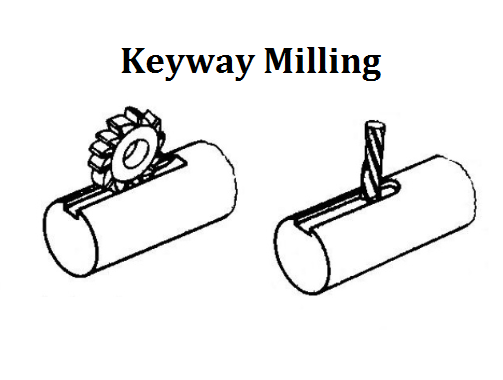 How to Cut a Keyway on a Milling Machine | Guide to Keyway Milling Operation & Cutters| CNCLATHING
 What is Axial Force – Axial Force Definition, Diagram, Formula (Equation) & How To Calculate?
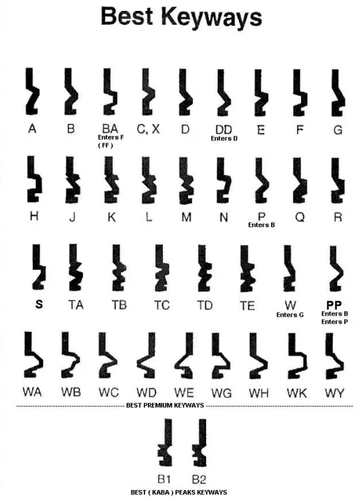 What is A Keyway – Lock Keyway Types, Designs & Schlage vs Kwikset | CNCLATHING
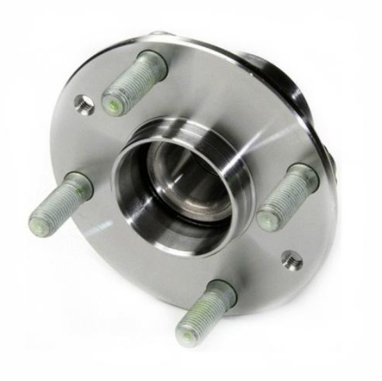 Guide to Automobile Hub: Materials, Manufacturing Technology and Difference
 ASME Flange Bolt Torque Chart (Calculation Formula & Sequence Pattern)