- Home
- Machining techniques
- CNC Machining Services
- Cooperative supply services
- Designs
- Materials
- Finishing Services
- Shop
- Products
- Guide
- About Us
- Contact Us
2021.3.5
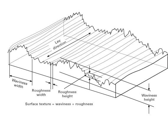

 Stainless Steel Families & Grades Chart (Chemical Composition, Properties & Uses)
 Machining Material Density Chart – Density Unit Conversion Table
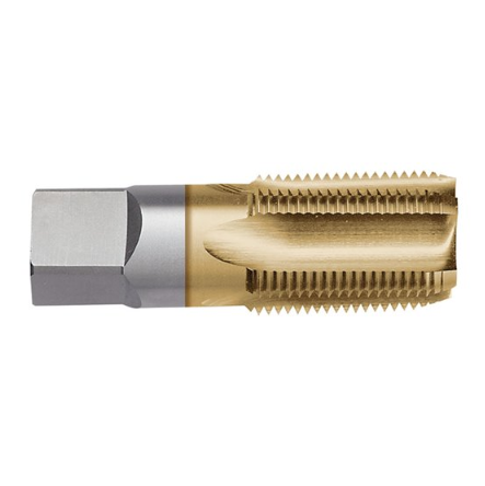 NPS Thread Dimensions Chart (NPSM & NPSL) | What Is Straight Pipe Thread
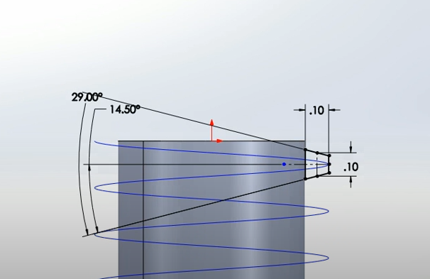 ACME Thread Dimensions Chart (Internal & External) | ACME Thread Profile, Formula, Classes & Sizes
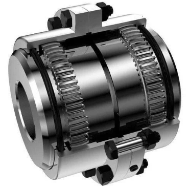 What Is Gear Coupling & How Does It Work – Full & Half Gear Coupling Size Chart
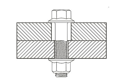 Clearance Hole Size Chart for Metric and Imperial Fasteners (Bolts, Screws & Studs)
