- Home
- Machining techniques
- CNC Machining Services
- Cooperative supply services
- Designs
- Materials
- Finishing Services
- Shop
- Products
- Guide
- About Us
- Contact Us
2021.6.19

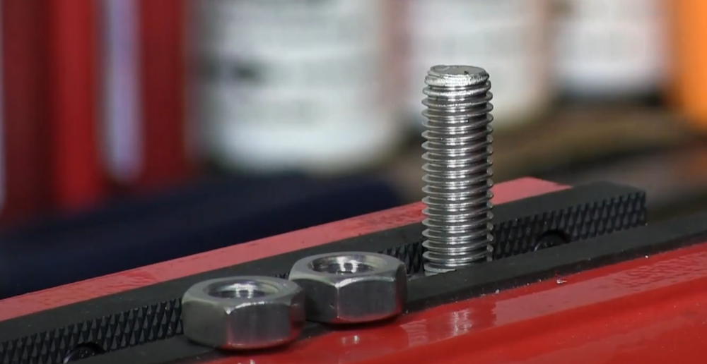
How to convert a precision milling machine to CNC(Computer numerical control)? let’s find out together! converting a machine to CNC is a simple three-step process. First, removing the lead screws lead screw nuts and handwheels. but most of the effort must be dedicated to focusing on installing ball screws, ball nuts, and stepper motors. most of the conversion kits need to be developed by disassembling this machine measuring all of its dimensions, designing and modeling all the components, and repeating the process until you are satisfied with the result.
Let’s take a look at the tools we’ll be using:
1.an assortment of metric Allen keys
2.pliers
3.flat head
4.Phillips head screwdrivers
5.seventeen & nineteen-millimeter wrenches
6.tape
7.calipers
8.drill
before we start installing Hardware, let’s talk about bearings for a minute. this kit uses angular contact bearings, which is a significant upgrade from the deep groove bearings and used on a first conversion project. angular contact bearings come in sets of two they must be installed with the correct orientation. they sometimes have color-coded seals and markings to identify the orientation. regardless you should always check your angular contact bearings with calipers.
Step One – Prep
Simply measure the thickness of the outer race on each side of the bearing. one side will be thinner than the other side. mark the thinner side, this is the side of the bearing that must face out or away from the flange. measure and mark all three sets, start with the z-axis. verify the z-axis is securely locked, partially thread in the four screws that attach the ball nut to the z-axis ball screw bracket. rotate the ball nuts so that it sits at the end of the ball screw. be careful not to unthread the ball nut all the way. doing so would unpack the ball nut. insert the ball screw assembly into the column, threaten the four screws in all the way and tighten them. both the ball nut bracket to the z-axis saddle using the socket head screwed. don’t tighten it all the way yet as we still need to align the bull nut. mount the two standoffs to the z-axis base using four socket head screws. pay careful attention to their orientation. these two need to be curved recesses to face each other. they match the circular protrusion on the stepper motor face. the two threaded holes need to be mounted towards the front of the column. they are used to mount an optional homing switch.
Step Two – Assemble
Next, wrap some tape around our bull screw. slide an angular contact bearing over the end of our bull screw with its mark sight facing down. slide the z-axis flange over the bearing and insert the second bearing with its marked side facing up. thread on the locking nut, carefully preload the angular contact bearings using a wrench and pliers. the tape keeps the pliers from barring the ball screw, the flange should spin freely with no binding. it is better to err on the side of too little peelers than too much preload. lock the knot to the ball screw shaft by tightening the grub screw and removed the tape. lower the z-axis flange flush with the top of the column and loosely thread in the four socket head screws. attach a drill securely to the end of the ball screw and unlock the z-axis while holding the drill. the drill keeps the bull screw from spinning freely and dropping the head when your lock the z-axis. we can now use the drill to raise the head. make sure they have clears the flange. lock the z-axis before removing the drill.
Step Three – Install The Stepper Motor
By the front case of the flange against the head of the machine while tightening its four mounting screws. this aligns the flange. we can now tighten the bull nut bracket the socket head screw. now we’re ready to install the stepper motor:
Slide the coupler over the end of the bull screw. align the stepper motor seated into place and secure to the standoffs with the four socket head screws. the couplers locked in place with its two clamping screws. install the cover plate on the column. the hole in the cover plate provides convenient access for lubricating our ball screw. with the z-axis finished in the head raised out of the way, we can now move on to the y-axis. start by bolting the y-axis brackets securely to the ball nut. rotate the ball screws, so that the bone is approximately five inches from the end of the ball screw. now insert the ball screw assembly under the saddle and through the hole in the base of the milling machine. thread the screw into the ball nut bracket, but don’t tighten it since we still need to align the ball nut. use calipers to probe our ball screw at two points as we slide the saddle back and forth. once the two points are within a few hundredths millimeter of each other, our ball nut is aligned and we can lock the ball nut brackets socket head screw. (a helpful tip is to hold the calipers in place with a piece of double-sided tape next wrap some tape)
Around our ball screw and slide an angular contact bearing over the end of the ball screw with its a mock sight facing back. slide the y-axis flange over the bearing, insert the second bearing with a smock side facing forward and thread the coupler onto the end of the ball screw. pull a couple apart and carefully preload the angular contact bearings using a screwdriver shaft and pliers. the flange should spin freely with no binding, lock the coupler to the ball screw by tightening its clamping screw and remove the tape, push the other half of the coupler back on. slide the saddle back until the flange bat against the base of the milling machine. loosely thread in the two socket head screws. translate the saddle forward by spinning the coupler. level the flange and lock it in place with the two socket head screws. we should be able to easily translate the saddle back and forth by hand without any binding. make additional adjustments as needed.
Step Four – Install The Stepper Motor
Insert the axle of the stepper motor into the coupler. use firm pressure to seat the axle all the way forward and clamp it in place. separate the coupler by pulling the stepper motor back. align the spacer with the face of the stepper motor. rejoin the coupler and securely mount the stepper motor using the four socket head screws. move on to the x-axis, start by bolting the ball nut to the x-axis ball nut bracket. spin the ball screws so that the ball nut is roughly at the midpoint of the bowl screws. slide the stepper motor coupler onto the end of the ball screw and lock it in place using the clamping screw. the stepper motor can be mounted on either end of the table. mount the stepper motor on the right to mount the ball screw bracket. so that the motor coupler is drawn right. before tightening the screws, use calipers to align the ball screw perfectly square with the saddle. the measurement at the left and right side of the saddle within a few hundredths millimeters of each other. tighten the ball nut bracket screws down firmly. clean the ways and slide the table back onto the saddle. be careful not to bump the ball screw. insert the Gib and lock it in place by using the Gib adjustment screw. the table should easily slide back and forth. wrap some tape around the end of a ball screw. slide an angular contact bearing over the end of the bull screw with its mark side facing back. slide the x-axis fins over the bearing and insert the second bearing with a small side facing forward. thread on the locking nut. carefully preload the angular contact bearings using a wrench and pliers. the flange should spin freely with no binding. lock the nut to the ball screw shaft by tightening the grub screw and remove the tape. mount the flange to the table using the two socket head screws. level the flange and tighten the screws all the way. push the bearing cover in place.
mount x-axis stepper motor. insert the axle of the stepper motor into the coupler. use firm pressure to seat the axle all the way forward and clamp it in place. separate the coupler by pulling the stepper motor back. mount the stepper motor flange to the table using two socket head screws. don’t tighten them yet, rejoin the coupler and mount the stepper motor to the fans using the four socket head screws. level the motor support flange and raise it slightly to compensate for the weight of the stepper motor. lock it in place by tightening the two socket head screws. install the Z and Y-axis covers.
 ASME Flange Bolt Torque Chart (Calculation Formula & Sequence Pattern)
 What is Jam Nut & Jam Nut vs Lock Nut vs Hex Nut
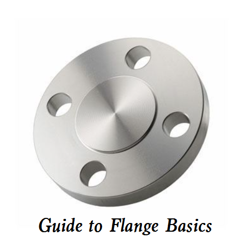 Guide to Flange Basics: Definition, Uses, Types, Sizes Explained & More
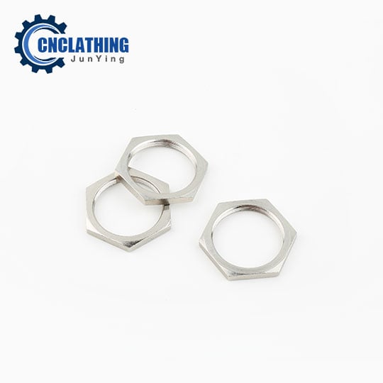 Different Types of Lock Nuts | How Do Lock Nuts Work | CNCLATHING
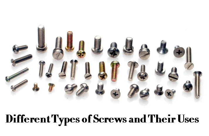 Different Types of Screws and Their Uses – Understanding Wood Screws, Machine Screws and More | CNCLATHING
 Ball Screw vs Lead Screw, What’s the Difference Between Them
