Runout tolerance is a key concept in geometric tolerancing (GD&T) used for controlling the variation in rotating parts during their operation. It ensures that CNC parts will run smoothly without wobbling or vibrating, which is essential for the reliability and precision of mechanical systems. This guide will explain the concept of runout tolerance, differentiate between circular runout and total runout, and provide usage guidelines.
What is Runout in GD&T?
In the ASME Y14.5 2018 standard, Runout tolerance is a type of geometric tolerance that limits the amount of variation or “wobble” in a rotating component’s surface as it turns around a datum axis. It is primarily used for cylindrical parts such as shafts, rollers, and collets, where regulating the surface variation is critical for the part’s functionality.
Unlike concentricity, which assesses the coaxiality of the cylindrical feature’s axis, runout tolerances focus on the surface deviations of the rotating component.
Also, be aware that runout tolerances are shape tolerances similar to roundness and cylindricity, but they require a datum axis to be specified because the controlled feature relates to that datum.
Types of Runout Tolerances
There are two types of runout tolerances:
- Circular Runout
- Total Runout
What is Circular Runout in GD&T?
Circular runout is defined as a tolerance zone in a plane perpendicular to the base axis, bounded by two concentric circles with their center lying on the base axis and spaced apart by the value of the circular runout tolerance. This means that when measuring a surface such as a shaft, the tolerance applies to a specific cross section at a time. You use a dial indicator at one location, make sure it runs true, and then repeat at other cross sections along the length. Each circular element must be within the specified tolerance at every measured cross section, but the individual cross sections are not compared to each other.
This approach allows for certain deviations such as tapering or “roller coaster” shapes along the length of the shaft, as long as each cross section individually satisfies the circular runout requirement. Circular runout controls the circularity of the feature at each measured location, but not the overall straightness or taper across the entire length.
Circular Runout Controls:
- Form, orientation (at cross-sections): Circular Runout (coaxial circles, 2D)
- Form: Circularity (2D)
- Location: Concentricity (median points/axis, 3D, Cylinder)
- Orientation/Form: Perpendicularity (planes, cylinders), Parallelism
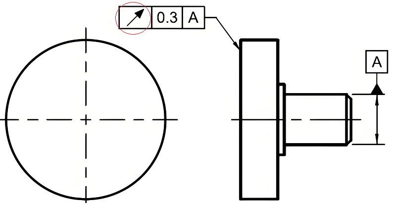
Circular Runout Symbol: ↗, which is used to indicate the difference between the maximum and minimum readings when the measured element rotates around the reference axis. It belongs to the runout tolerance in the form and position tolerance.
How to Use Circular Runout Tolerance?
Radial Direction: To control the radial displacement, you don’t include a diameter symbol (φ) before the tolerance value because the tolerance zone is defined by two concentric circles.
Axial Direction: For controlling displacement in the axial direction, the tolerance is indicated without the diameter symbol and is defined by two parallel lines.
How To Measure Circular Runout?
When inspecting circular runout, all cross sections must be within the specified tolerance zone. The number of cross sections measured depends on the quality plan, balancing risk and cost. Functionally, every cross section should conform, but the process may sample a certain number based on inspection strategy.
What is Total Runout in GD&T?
Total runout, on the other hand, is a 3D specification that applies to the entire surface of a feature. The tolerance zone for total runout is two concentric cylinders extending the full length of the feature. This controls not only the circularity at various cross sections but also the overall straightness, cylindricity, and taper of the surface. The total runout tolerance is the difference between the largest and smallest distance of all points on the real surface, measured in the reference section, from the base axis.
For planar surfaces perpendicular to the datum axis, total runout is defined by the difference between the largest and smallest distances from the points on the surface to a plane perpendicular to the base axis. Here, the tolerance zone consists of two parallel planes. This also controls the perpendicularity of the surface relative to the base axis.
Total Runout Controls:
- Form, off-center/orientation: Circular Runout (coaxial circles, 2D)
- Form: Cylindricity (shape, 2 cylinders, 3D), Circularity (2D), Straightness
- Location: Concentricity (median points/axis, 3D, Cylinder)
- Orientation/Form: Perpendicularity (planes, cylinders), Parallelism
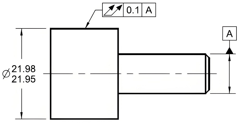
Total Runout Symbol: ↗_↗It consists of two upward-slanting arrows connected by a short horizontal line at the end, which is different from the single arrow symbol with a circular jump.
How to Use Total Runout Tolerance?
Radial Direction: The indication for total runout is similar to circular runout, but evaluates the entire surface’s displacement during rotation. The tolerance zone is between two concentric cylinders.
Axial Direction: For axial displacement control, the entire end face variation is limited, and the tolerance zone is between two parallel planes.
How To Measure Total Runout?
For total runout, measurements are taken along the entire feature, capturing any form deviation such as straightness or taper. This involves moving the dial indicator along the surface and recording the total indicator reading (TIR), ensuring it remains within the specified tolerance.
Total Runout vs Circular Runout: What Are the Differences Between Them?
Key differences between circular and total runout in GD&T:
Circular runout applies to individual cross sections, controlling the roundness at each location but not the cumulative effect along the length.
Total runout applies to the entire surface, controlling roundness, straightness, cylindricity, and taper in all directions.
Circular runout allows for some deviation between cross sections, while total runout restricts such deviations by enforcing consistency across the entire feature.
On planar surfaces perpendicular to the axis, total runout and perpendicularity are equivalent; however, circular runout is not the same as perpendicularity.
Total Runout vs Circular Runout: Differences in Practical Applications & Measurement
Circular runout is suitable for checking individual sections of a cylindrical or conical surface where control of form along the length is not required. Total runout is more appropriate when overall surface integrity, including form and orientation, must be maintained along the entire length or face of the feature.
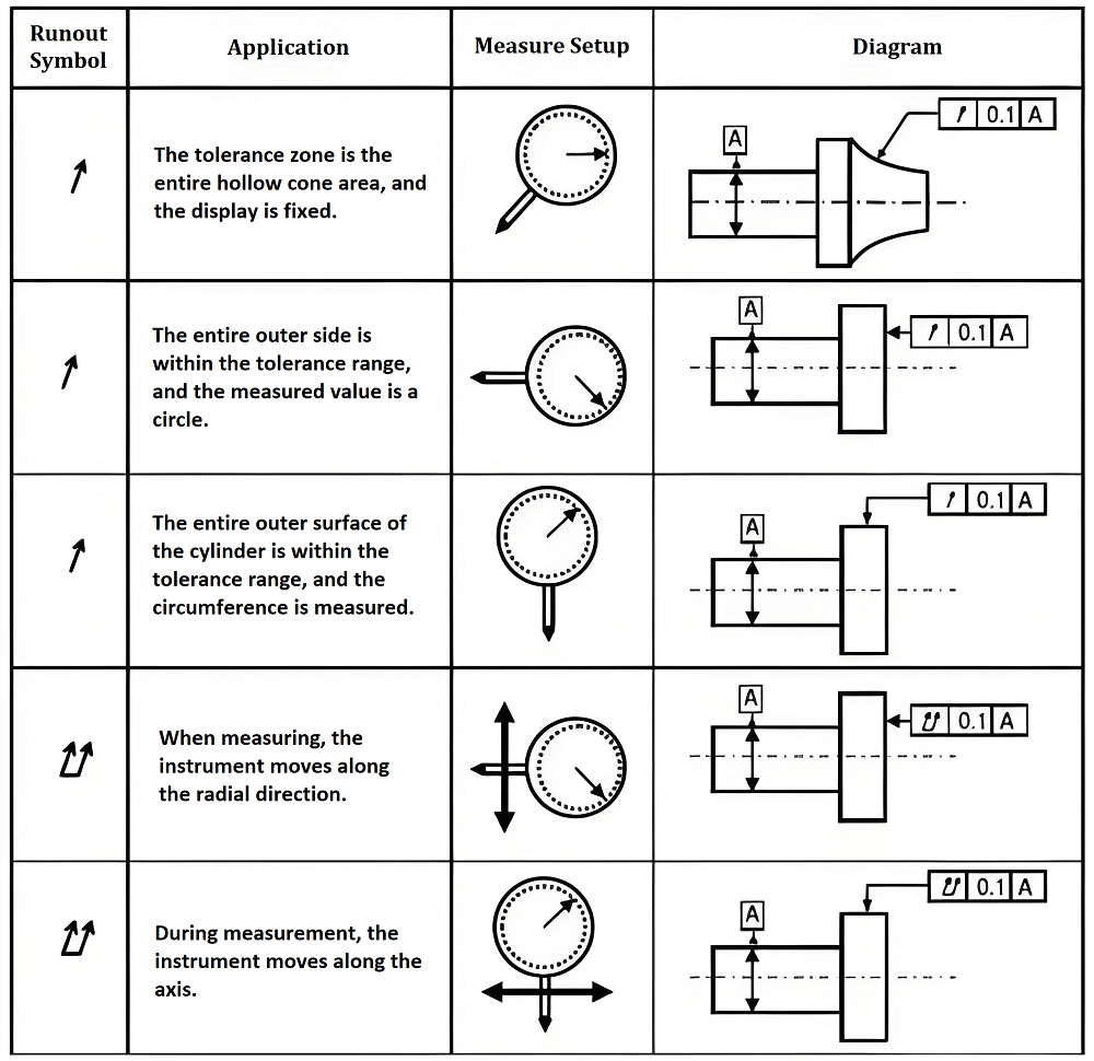
Runout tolerances are essential in ensuring that rotating parts operate smoothly and within acceptable limits of variation. When designing and inspecting parts, it’s critical to understand the type of runout required for the application and how to correctly specify it on technical drawings.
By following the guidelines above, engineers and machinists can effectively apply and measure runout tolerances to maintain the quality and functionality of rotating components.


