
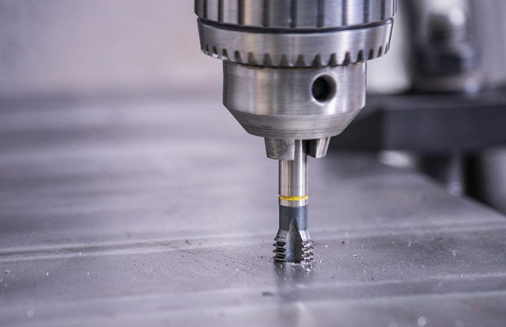
Tapping, as a method for thread machining, mainly relies on the use of a tap. The process is similar to traditional methods, with the key being to ensure that, as the tap feeds in and out, it rotates once and advances by one pitch in the feed direction. Tapping uses the tap to process threads in the workpiece; this process is a type of form tool machining, characterized by high rigidity. The core technology lies in the rotation and feed of the tap, a process precisely controlled by CNC milling machines to guarantee efficient and high-quality production. But how to calculate tapping speeds and feeds? Here, we will help you thoroughly understand these concepts, not only explaining their definitions and calculation formulas, but also providing general reference tables and calculation tools to help you determine specific data!
What are CNC Tapping Speeds and Feeds?
Tapping speeds and feeds are key parameters in machining that control the movement of the tap, directly affecting machining efficiency and thread quality.
Tapping Speeds (Spindle Speed/RPM)
Cutting speed refers to the linear speed of the tap as it rotates, usually measured in meters per minute (m/min). Different materials and processes have clear requirements for cutting speed, such as:
- Steel: 6–15 m/min (tempered steel or hard steel: 5–10 m/min)
- Stainless steel: 2–7 m/min
- Cast iron: 8–10 m/min
- High-speed tapping: 100–150 m/min (for small-diameter threads)
Tapping Feed Rates
Feed rate refers to the axial movement speed of the tap, which must be matched to the cutting speed to maintain synchronized feed. Rigid tapping cycles use CNC control to synchronize spindle rotation and feed, ensuring precise thread pitch. If the machine cannot precisely match the tap pitch, it may cause thread errors or tap damage.
Influencing Factors To Tapping Feed & Speed
- Material Hardness: The higher the hardness, the lower the cutting speed should be to prevent rapid tap wear.
- Hole Size: Small holes (e.g., <30mm) are suitable for high-speed tapping, but speed and feed must be controlled to avoid vibration.
- Lubrication: Using lubricants such as oil or emulsions can extend tap life and improve efficiency.
Why are Speeds and Feeds Important in CNC Tapping?
In tapping, a proper match of speed and feed is critical. Spindle speed (RPM) and feed rate determine whether the cutting process is smooth, directly affecting thread accuracy, surface quality, and tap life. If the speed is too high or feed is not synchronized, it can easily cause tap breakage, thread errors, or chip entanglement. When feed and spindle speed are synchronized, it ensures consistent and accurate threads and effectively prevents issues such as thread cresting. Therefore, only by properly setting tapping speed and feed can you improve machining efficiency, extend tool life, and guarantee final product quality.
How To Calculate Tapping Speeds and Feeds?
1. CNC Tapping Speed Calculation Formula (Surface Speed to RPM and SFM)
Spindle speed for tapping is calculated based on the recommended surface speed (SFM or m/min) for the material and the tap diameter:
- Metric Tapping Speed Formula: RPM = (V × 1000) / (π × D)
V = surface speed in m/min
D = thread major diameter in mm - Imperial Tapping Speed Formula: RPM = (SFM × 3.82) / D
SFM = surface speed in ft/min
D = thread major diameter in inches
3.82 ≈ 12 / π
In actual use, the cutting speed Vc should be selected according to the material, hardness, and tool performance. Generally, harder materials require a lower cutting speed to ensure tool life and machining quality.
2. CNC Tapping Feed Rate Calculation Formula (IPM and mm/min, Tapping is Synchronous with Pitch)
Tapping feed rate is calculated as the product of threads per revolution (pitch) and spindle speed.
- Metric (mm): Feed Rate (mm/min) = Pitch (mm) × RPM
(Pitch = distance between threads in mm) - Imperial (inches): Feed Rate (IPM) = RPM ÷ TPI
(TPI = Threads Per Inch)
In practice, the feed per revolution (FPR) should be chosen according to thread specifications, tool pitch, and machining accuracy. Generally, coarser threads require a larger feed per revolution to improve efficiency, while finer threads need a smaller feed per revolution to ensure accuracy.
CNC Tapping Speeds & Feeds Calculator (Metric/Imperial)
Based on the above formulas and key factors affecting CNC tapping, we have developed a Tapping Speeds & Feeds Calculator for convenient parameter calculation in routine projects.
CNC Tapping Speeds & Feeds Calculator
widgetInputs
Feed = pitch × RPM (or RPM ÷ TPI). Use a Safety Factor below 1.0 if not rigid tapping or in gummy materials.
Outputs
RPM = (V × 1000) / (π × D) [metric] • RPM = (SFM × 3.82) / D [imperial]. Feed = Pitch × RPM (or RPM ÷ TPI).
HSS/Carbide Tapping Speeds and Feeds Chart (Aluminum/Steel)
To help readers better understand and apply the above methods, this article provides a tapping speeds chart for reference. The table lists recommended cutting speeds and RPM ranges for different materials, hardness, and tap diameters. In practice, you can use the data in the table to select the appropriate cutting speed and RPM for tapping. The table also provides common thread specifications and corresponding feed per revolution ranges for reference.
The selection of tap speed (unit: r/min) and feed (unit: mm/r) should take into account the material hardness, tap type, and thread specification. The table below is based on actual industry data from 2024 and is suitable for through-hole thread tapping in common metals (for blind holes, reduce speed by 15%–20%).
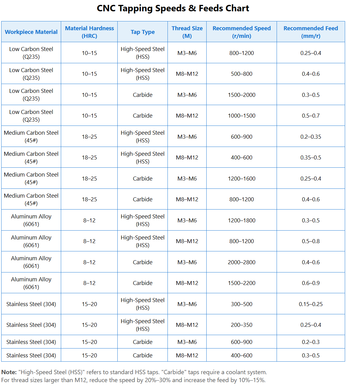
Note:
- “High-Speed Steel (HSS)” refers to standard HSS taps; carbide taps require a cooling system.
- For thread sizes over M12, reduce speed by 20–30% and increase feed by 10–15%.
- Tapping speed and feed calculations and parameter selection should be adjusted and optimized according to the actual situation. For special shapes or sizes, special tools and parameters may be required; for mass production, more efficient schemes may be needed. Always analyze and judge according to actual conditions.
Tap Speed and Feed Adjustment Methods for The Specific Projects
Initial Parameter Setting Steps
- Step 1: Determine the material and hardness, and select the base parameter range from the “Core Tapping Speeds and Feeds Chart.” For example, for 45# steel (HRC20) M8 thread, the base RPM range is 400–1200 r/min, feed is 0.35–0.6 mm/r.
- Step 2: Narrow down the range according to tap type. For HSS taps, set speed to 400–600 r/min, feed to 0.35–0.5 mm/r; for carbide taps, set speed to 800–1200 r/min, feed to 0.4–0.6 mm/r.
- Step 3: Adjust for working conditions. For blind holes, reduce speed by 15% (e.g., HSS tap speed becomes 340–510 r/min), keep feed unchanged. If machine rigidity is poor, reduce speed by another 10% (306–459 r/min) to prevent vibration and maintain thread accuracy.
Test Cutting and Verification Tips
- Tip 1: For the first test cut, use the lower end of the parameter range. For example, for M6 aluminum thread, start with 1200 r/min and 0.3 mm/r feed, and observe for abnormal noise, smoke, etc.
- Tip 2: After test cutting, check thread quality with a go/no-go gauge. If the thread passes and has no burrs, gradually increase speed (by 10–15% each time) until efficiency and quality are balanced.
- Tip 3: Record the optimal parameters. For different materials, specifications, and tap types, establish a dedicated parameter archive. Practice in a 2024 auto parts plant showed that after archiving, tap replacement frequency dropped by 30% and qualification rate rose to 99.2%.
Rigid Tapping Speeds and Feeds
To improve efficiency and thread accuracy, rigid tapping technology is sometimes used. Rigid tapping synchronizes spindle rotation and Z-axis feed, ensuring a strict ratio between them. During rigid tapping, monitor spindle position deviation and instantaneous sync errors, and adjust control parameters like loop gain and acceleration/deceleration time constants as needed to ensure quality.
What is Rigid Tapping?
Rigid tapping, also called “synchronous feed tapping,” synchronizes spindle rotation and feed to meet specific thread pitch requirements. Since feed is synchronous, tension-compression tap holders should not be used. A major advantage of rigid tapping is precise depth control in blind holes. Use tap holders with adequate compensation to ensure long tap life and precise depth control.
Rigid Synchronous Tapping Feeds and Speeds Adjustment:
During tapping, ensure the feed matches spindle speed so feed and spindle revolution match thread pitch perfectly. This not only controls thread depth precisely but also ensures dimensional consistency and avoids cresting.
Mastering the formulas and parameter settings for tapping speeds and feeds is critical to improving thread quality. In practice, adjust flexibly according to specific conditions and needs for the best results.
Common Problems and Solutions About CNC Tapping Speed & Feed Setting
Tap Wears Out Too Fast
- Reason 1: Speed too high, causing cutting temperature to exceed tap’s heat limit. For example, tapping M6 threads in 304 stainless steel at over 900 r/min with HSS taps will show significant wear in 10 minutes. Lower speed to 300–500 r/min.
- Reason 2: Feed too low, so the tap rubs instead of cuts. For example, tapping M8 in Q235 steel with feed below 0.4 mm/r increases bottom edge wear. Adjust feed to 0.4–0.6 mm/r.
Thread Accuracy Not Up to Standard
- Reason 1: Feed fluctuation, causing pitch errors. For example, in 6061 aluminum M6 threads, if feed drops suddenly from 0.4 to 0.3 mm/r, the thread pitch diameter will be off. Check the feed system to ensure stable feed speed.
- Reason 2: Speed too low, causing excessive cutting force and tap deformation. For example, in 45# steel M12 threads below 400 r/min, HSS taps may bend. Increase speed to 400–600 r/min and use coolant.
Tap Breakage
- Reason 1: Speed too high and feed too large, causing cutting load to exceed tap strength. For example, in 304 stainless steel M8 at 600 r/min and 0.5 mm/r feed, carbide taps may break. Lower speed to 400–600 r/min, feed to 0.3–0.5 mm/r.
- Reason 2: Blind hole tapping without depth control, causing tap to collide with hole bottom. In programming, set depth limits. For an M8 blind hole 15mm deep, set feed depth to 13mm (leave a 2mm safety margin).
Related Articles:
 What Is a Blind Flange – Blind Flange Dimensions Chart in MM & Inch (Class 150 to 2500)
 Knuckle Thread Form, Standard, Uses, Angle, Diagram, Drawing and Dimensions Chart
 How To Remove a Broken Tap in CNC Machining?
 ACME Thread Dimensions Chart (Internal & External) | ACME Thread Profile, Formula, Classes & Sizes
 What Is UNS Thread – UNS Thread Meaning, Standard, Fit Classes & Dimensions Chart
 Types of Nut Fasteners and Uses – Nut Size Chart & Dimensions Standards